


I-13
Names and Functions of Parts
Chapter 1 Overview
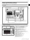
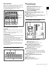
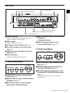
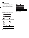
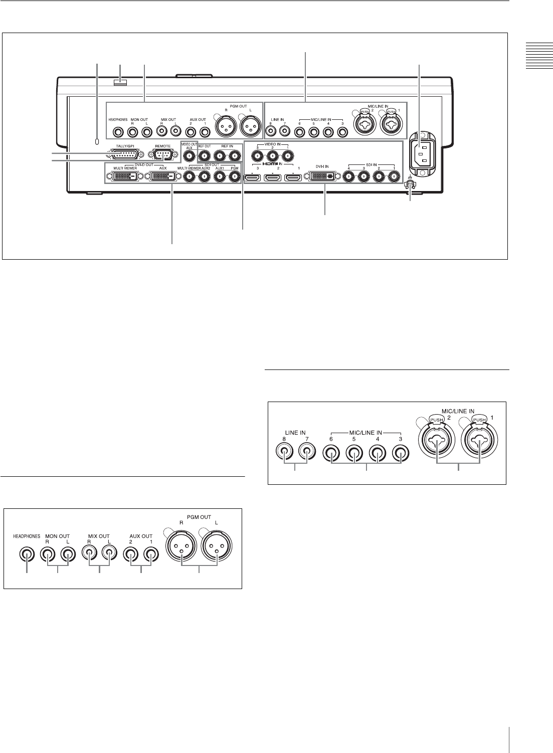
Rear Panel
a Anti-theft cable slot
Connect a commercially available anti-theft cable
(3 mm × 7 mm) here to prevent theft.
b USB connector
Connect a USB flash drive here.
c AC IN (power input) connector (page I-16)
d TALLY/GPI connector (15-pin D-sub, male)
(page I-42)
e REMOTE connector (RS-232C, 9-pin D-sub,
male) (page I-42)
f Ground connector
Connect the system grounding wire here.
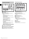
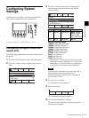
1 Audio Output Block
a HEADPHONES connector (standard stereo
phone) (page I-33)
b MON OUT (monitor output) L and R connectors
(TRS phone) (page I-33)
c MIX OUT (mix output) L and R connectors
(phono jack) (c Advanced Settings)
d AUX OUT (auxiliary output) 1 and 2 connectors
(TRS phone)
(c Advanced Settings)
e PGM OUT (program output) L and R
connectors (XLR, male) (page I-33)
2 Audio Input Block
a LINE IN (line input) 7 and 8 connectors (phono
jack) (page I-21)
b MIC/LINE IN (microphone/line input) 3 to 6
connectors (TRS phone) (page I-21)
c MIC/LINE IN (microphone/line input) 1 and 2
connectors (XLR, female/TRS phone combo)
(page I-21)
These do not supply power (e.g., for condenser
microphones).
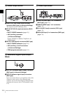
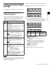
3
1
4
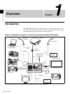
5 Video input block (page I-14)
2
5
1 Audio output block (page I-13)
6
3 Video output block (page I-14)
2 Audio input block (page I-13)
4 Reference signal input/output block (page I-14)
1234 5
12 3