


I-23
Configuring Multi Viewer Settings
Chapter 2 Preparations
Configuring Multi Viewer
Settings
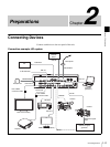
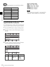
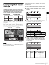
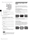
The Multi Viewer allows you to display multiple video
inputs, program video outputs, and preview video outputs
simultaneously on a monitor connected to the unit. A
4-screen layout and a 10-screen layout are available.
(The numbers indicate the number assignments for each
sub-screen.)
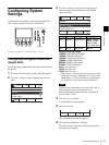
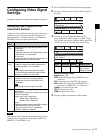
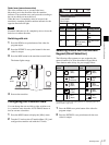
Multi Viewer output example: 10-screen layout
Red frames indicate the sub-screens for video inputs that
are currently on air (i.e., the program video).
If a frame memory key is on air, the red frame appears in
the [FM-V] (video) sub-screen.
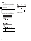
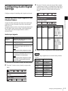
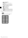
When using the Multi Viewer, specify the video output for
each sub-screen.
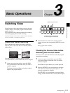
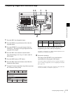
1
Press the SETUP button to display the [Setup] menu.
2
Turn the V1 knob to select [Multi Viewer], and press
the knob.
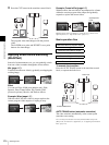
3
Turn the V1 knob to select [Viewer Mode], and turn
the V4 knob to select the split-screen layout.
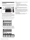
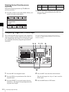
4
Turn the V1 knob to select the sub-screen ([Signal
Assign 1] to [Signal Assign 10]) to which you want to
assign the video signal, and turn the V4 knob to select
the video signal.
4-screen layout 10-screen layout
Note
12
3 4
12
3 5
4
6
7 8910
KEY SOURCE
PVW
PGM
SDI1 SDI2
SDI3 ColBg
Black
H/V2
DVI
H/V1
Preview video Program video
Red frame
Knob Parameter Meaning Setting
values
V4 Split Split-screen
layout
4, 10
Knob Parameter Meaning Setting values
V4 Source Video
signal
Black, SDI1 to 4,
DVI, H/V1 to 3,
ColBg, FM-V, FM-K,
PGM, PVW,
Aux1PG, Aux1PV,
Aux2PG, Aux2PV
0001
Rate
30
SS
Mon
PGM
Setup
8/11
Select
Video (Misc)
Multi Viewer
GPI/Tally
Information
Enter
0001
Rate
30
SS
Mon
PGM
Multi Viewer
1/11
Select
Split
10
Back
Viewer Mode
Signal Assign 1
Signal Assign 2
0001
Rate
30
SS
Mon
PGM
Multi Viewer
2/11
Select
Source
PVW
Back
Viewer Mode
Signal Assign 1
Signal Assign 2