


I-24
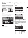
Configuring Multi Viewer Settings
Chapter 2 Preparations
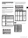
Notes on setting values
Black: Black video
SDI1 to 4: Video input from the SDI IN 1 to 4
connectors
DVI: Video input from the DVI-I IN connector
H/V1 to 3: Video input from the HDMI IN 1 to 3
connectors or VIDEO IN 1 to 3 connectors
ColBg: Color background video
FM-V: Frame memory video
FM-K: Frame memory key
PGM: Program video output
PVW: Preview video output
Aux1PG: Program video output of the Aux1 bus
Aux1PV: Preview video output of the Aux1 bus
Aux2PG: Program video output of the Aux2 bus
Aux2PV: Preview video output of the Aux2 bus
5
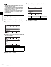
Repeat step 4 to configure the other sub-screens.
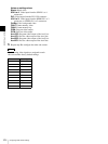
The following video signals are assigned to each
sub-screen under factory default settings.
Tip
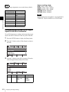
Sub-screen Video signal
1 PVW
2PGM
3 SDI1
4SDI2
5SDI3
6SDI4
7DVI
8 H/V1
9H/V2
10 H/V3