


I-19
Configuring Video Signal Settings
Chapter 2 Preparations
Configuring Video Signal
Settings
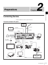
Configure settings for handling video signals on the unit.
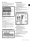
Assigning Video Signals to the
Cross-Point Buttons
Assign the video signals that are input to the video input
connectors on the rear panel of the unit and the unit’s
internal signals to cross-point buttons 1 to 8 (PGM and
PST/KEY) in the cross-point control block.
Only signals of the format that is specified under [System
Format] in the [Setup] menu can be input for SDI 1 to 4,
HDMI 1 to 3, and VIDEO 1 to 3.
1
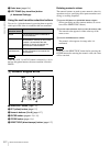
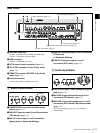
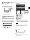
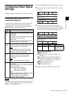
Press the SETUP button to display the [Setup] menu.
2
Turn the V1 knob to select [Video (XPT)], and press
the knob.
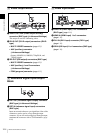
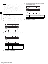
3
Turn the V1 knob to select the number of the
cross-point button ([XPT Assign 1] to [XPT Assign
14]) to which you want to assign the video signal, and
turn the V4 knob to select the video signal source.
Notes on setting values
Black: Black video
SDI1 to 4: Video input from the SDI IN 1 to 4
connectors
DVI: Video input from the DVI-I IN connector
H/V1 to 3: Video input from the HDMI IN 1 to 3
connectors or VIDEO IN 1 to 3 connectors
ColBg: Color background video
FM: Frame memory video
PGM: Program video output
4
Repeat step 3 for assignments to other buttons.
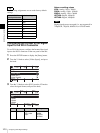
Signal
name
Description
SDI
1 to 4
The signals that are input differ depending on the
system mode.
For SD mode:
Assign the video of the SDI signals that are input
to the SDI IN 1 to 4 connectors.
For HD mode:
Assign the video of the HD SDI signals that are
input to the SDI IN 1 to 4 connectors.
HDMI
1 to 3
For HD mode:
Assign the video of the HDMI signals that are
input to the HDMI 1 to 3 connectors.
Notes
• These signals cannot be used in SD mode.
• Content with High-bandwidth Digital Content
Protection (HDCP) cannot be used.
VIDEO
1 to 3
For SD mode:
Assign the video of the analog composite
signals that are input to the VIDEO 1 to 3
connectors.
Note
These signals cannot be used in HD mode.
DVI-I The signals that are input differ depending on the
system mode.
Assign the video of the DVI-I signals that are input
to the DVI-I connector.
Analog: XGA (1024 × 768) 60 Hz,
SXGA (1280 × 1024) 60 Hz,
WXGA (1280 × 768) 60 Hz
Digital:
When the system format is 720p/59.94, 720p/50,
480i/59.94, 576i/50: Cannot be used.
When the system format is 1080i/59.94,
1080i/50: 1080p/50, 1080p/60
Note
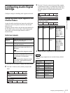
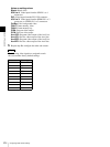
Knob Parameter Meaning Setting values
V4 Source Video signal Black, SDI1 to 4,
DVI, H/V1 to 3,
ColBg, FM, PGM
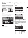
0001
Rate
30
SS
Mon
PGM
Setup
5/11
Select
Audio
Video (Input)
Video (XPT)
Video (Output)
Enter
0001
Rate
30
SS
Mon
PGM
Video (XPT)
1/15
Select
Source
SDI1
Back
XPT Assign 1
XPT Assign 2
XPT Assign 3