


I-42
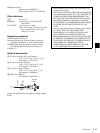
Specifications
Appendix
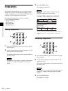
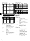
Pin Configurations
TALLY/GPI connector
15-pin D-sub, male
REMOTE connector
RS-232C, 9-pin D-sub, male
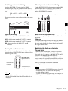
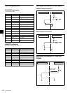
Example Connection of GPI Input
Switch or relay connection
Open collector connection
Example Connection of Tally/GPI
Output
Pin No. Signal name Description
1 GPO1 GPI output 1 / tally 1
2 GPO2 GPI output 2 / tally 2
3 GPO3 GPI output 3 / tally 3
4 GPO4 GPI output 4 / tally 4
5 GPO5 GPI output 5 / tally 5
6 GPO6 GPI output 6 / tally 6
7 GPO7 GPI output 7 / tally 7
8 GPO8 GPI output 8 / tally 8
9GNDGND
10 GND GND
11 GPI1 GPI input 1
12 GPI2 GPI input 2
13 GPI3 GPI input 3
14 GPI4 GPI input 4
15 GND GND
Pin No. Signal name Description
1 – No Connection
2 RX Received Data
3 TX Transmitted Data
4 DTR Data Terminal Ready
5 GND Ground
6 DSR Data Set Ready
7 RTS Request to Send
8 CTS Clear to Send
9 – No Connection
External device MCS-8M
10 kΩ
1 kΩ
External device MCS-8M
10 kΩ
1 kΩ
External deviceMCS-8M
Maximum voltage: 5 V
Maximum load
current: 5 mA