


1-22
VPL-CS2/CX1
GB
42
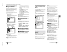
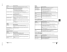
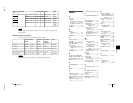
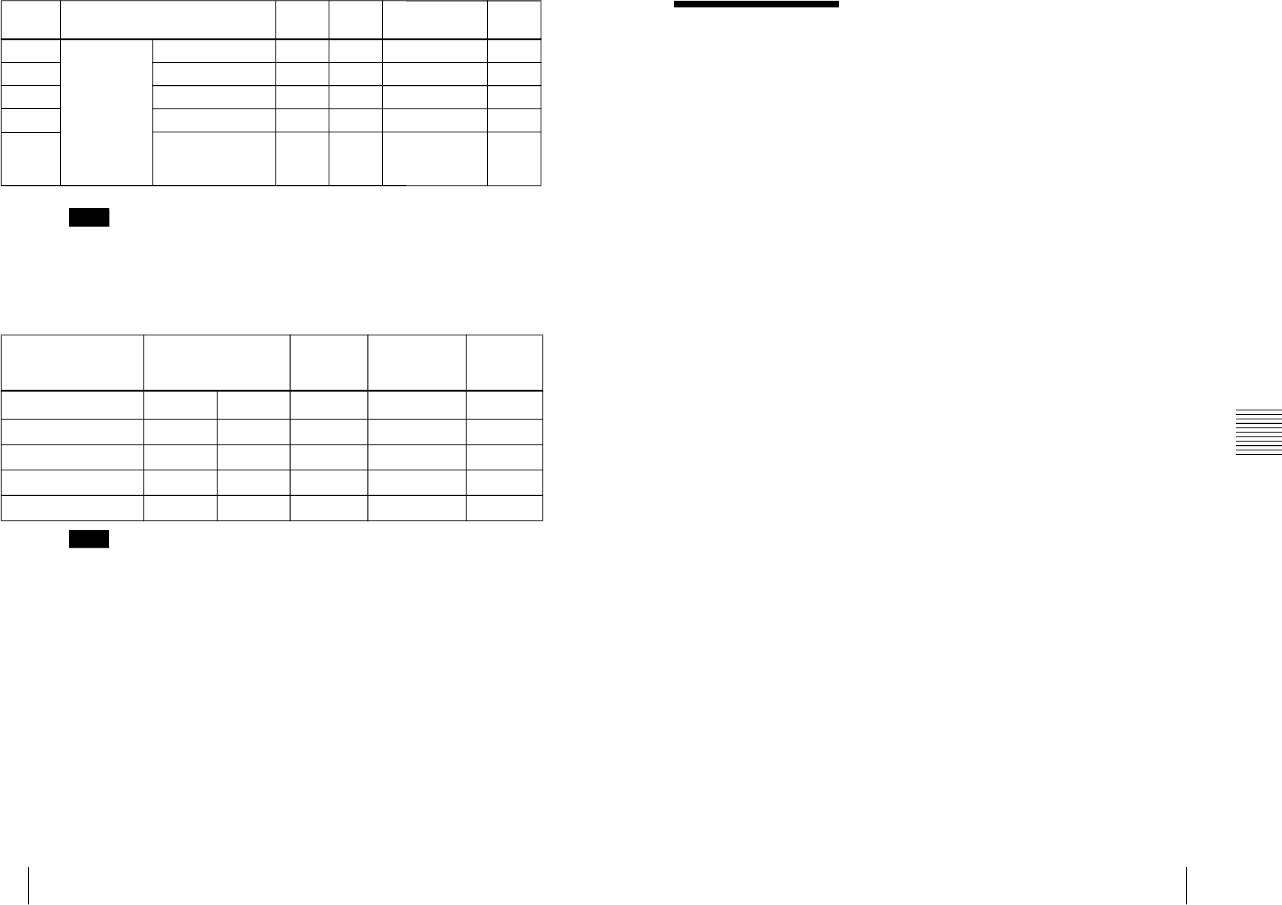
Specifications
Whan a signal other than the preset signals shown above is input, the picture may not
appear properly.
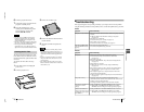
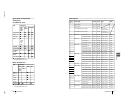
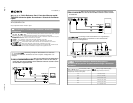
Warning on power connection
Use a proper power cord for your local power supply.
1) Use an appropriate rating plug which is applied to local regulations.
34 1280 × 1024 SXGA VESA 43 Hz 46.433 43.436 H-pos, V-pos 1696
35 SGI-5 53.316 50.062 S on G 1680
36 SXGA VESA 60 Hz 63.974 60.013 H-pos, V-pos 1696
37 SXGA VESA 75 Hz 79.976 75.025 H-pos, V-pos 1688
38 SXGA VESA 85 Hz 91.146 85.024 H-pos, V-pos
1012
(VPL-CS2)
1296
(VPL-CX1)
Note
The United States,
Canada
Continental
Europe
UK, Ireland,
Australia,
Newzealand
Japan
Plug type VM0233 290B YP-12A
—
1)
VM1296
Female end VM0089 386A YC-13B VM0310B VM10505
Cord type SJT SJT H05VV-F N13237/CO-228 HVCTF
Rated Voltage & Current 10A/125V 10A/125V 10A/250V 10A/250V 13A/125V
Safety approval UL/CSA UL/CSA VDE VDE DENTORI
Note
Memory
No.
Preset signal fH (kHz) fV (Hz) Sync SIZE
43
GB
Index
Other
Index
A
Adjuster ..........................10
Adjusting
memory of the settings 26
the picture .............23, 27
the picture size/shift ....28
Air filter ..........................32
ASPECT .........................29
B
Battery
installation ..................14
notes ............................14
BRIGHT .........................27
C
Carrying handle ................9
COLOR ..........................27
COLOR SYS (System) ...27
COLOR TEMP ...............27
Connections
component equipment 18
computer .....................16
VCR ............................18
CONTRAST ...................27
D
D. (Dynamic) PICTURE 27
DIGITAL KEYSTONE ..30
Digital Zoom Function ...25
DOT PHASE ..................28
G
GAMMA MODE ...........27
H
HUE ................................27
I
INPUT A connector .......12
pin assignment ............39
INPUT SETTING menu .28
INPUT-A ........................30
Installation examples ......15
notes ............................36
unsuitable conditions ..36
K
KEYSTONE MEMORY 30
L
Lamp replacement ..........31
LAMP TIMER ...............30
LANGUAGE .................30
selecting the menu
language ..............20
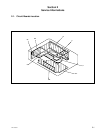
Location and function of
controls
connector panel ..........12
control panel ...............11
front/left/bottom side ....9
rear/right side ................9
Remote Commander ...13
M
Menu
clearing the menu
display .................26
INPUT SETTING
menu ...................28
PICTURE CTRL
menu ...................27
SET SETTING menu .30
using the menu ...........26
Message
caution ........................35
warning .......................35
Mouse cable
connection ..................18
pin assignment ............39
Mouse connector ............12
pin assignment ............39
O
Optional accessories .......38
P
PICTURE CTRL menu ..27
Pin assignment ...............39
Power
turn on ........................22
POWER SAVING ....11, 30
Precautions .......................6
R
Remote Commander ......13
battery installation ......14
location and function of
controls ...............13
Remote control detector
front ..............................9
rear ...............................9
setting .........................30
Reset
resetting the item ........26
resttable items .............26
S
SCAN CONV (Scan
converter) ................28
Screen size ...............15, 37
SET SETTING menu .....30
SHARP ...........................27
SHIFT ............................28
SIRCS RECEIVER ....9, 30
SIZE ...............................28
Specifications .................37
STATUS (on-screen
display) ...................30
Supplied accessories ......38
T
Troubleshooting .............33
U
USB connector .........12, 17
V
Ventilation holes
exhaust ..........................9
intake ......................9, 10