


3-1
VPL-CS2/CX1
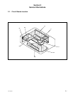
Section 3
Electrical Adjustments
3-1. Preparations
3-1-1. Equipment Required
. Oscilloscope
Tektronix 2465 or equivalent
(bandwidth: 350 MHz or more)
. NTSC, PAL, SECAM component signal generator
Tektronix TG2000 + AVG1 (optional module) + AWVG1
(optional module) or equivalent
. VG (Programmable video signal generator)
VG814 or equivalent
. Digital voltmeter
Advantest TR6845 or equivalent
. Luminance meter
Note: Perform the following adjustments at least 5 minutes
after turning on the power.
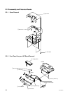
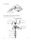
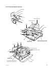
3-1-2. Optical Unit Adjustment
Drive the cooling fan and turn on the lamp.
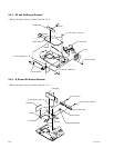
1) Mirror Adjustment
Set the screen size to 80-inch at the wide-end.
1. Set the unit in green-only.
2. Adjust the blanking sections at the top, bottom, left,
and right for minimum by moving the adjusting plate
of the G-channel mirror (OPT).
3. Tighten the adjusting plate fixing screws.
4. Set the unit in cyan.
5. Adjust the blanking sections at the top, bottom, left,
and right for minimum by moving the adjusting plate
of the B-channel mirror (OPT), and then maximize the
intensity of the blue.
6. Tighten the adjusting plate fixing screws.
7. Set the unit in all white.
8. Adjust the blanking sections at the top, bottom, left,
and right for minimum by moving the adjusting plate
of the R-channel’s first mirror (OPT), and then
maximize the intensity of the red.
9. Tighten the adjusting plate fixing screws.
10. Secure the six adjusting plate fixing screws using a
torque screwdriver.
Tightening torque: 8 kgf/cm
11. Make sure that the deviation of the lighting range is
within the specific range.
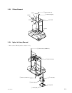
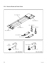
2) Polarizing Plate Adjustment
1. Attach the extension cable and the extension flexible
cable to the C board, and input the RGB all black
(SVGA 0 IRE Flat Field) signal.
2. Move the red, green, and blue polarizing plates
gradually to adjust the black level.
3. Secure the fixing screws using the screwdriver.
Note: When tightening the six fixing screws, be sure to push
the polarizing plate toward the radiating side.
3-1-3. Factory Mode Setting
1. Make sure that the STATUS in the menu is ON.
2. Exit the menu.
3. Press the keys in the following ORDER:
“ENTER” → “ENTER” → “LEFT” → “ENTER”
4. The message “Do you wish to enter into the
FACTORY MODE?” will be displayed.
5. Select YES.
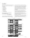
3-2. V-COM Adjustment
1. Input the green-only 50 IRE all white signal to
INPUT-A.
2. Set the CONTRAST to 50 and BRIGHT to 50.
3. Set the screen to G VCOM adjustment of “Device
Adjust.”
Adjust the G VCOM so that the vertical line on the
screen is minimum.
4. Input the red-only and blue-only 50 IRE all white
signal respectively and adjust R VCOM and B VCOM
respectively so that the vertical line becomes
minimum.
5. Save the value adjusted.