


1
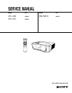
VPL-CS2/CX1
Table of Contents
1. Operating Instructions
Operating Instructions ............................................................................................ 1-1
Quick Reference Card ..........................................................................................1-24
2. Service Informations
2-1. Circuit Boards Location ..............................................................................2-1
2-2. Disassembly and Extension Boards ............................................................2-2
2-2-1. Cover Removal...........................................................................2-2
2-2-2. Front Panel Assy and NF Board Removal ................................. 2-2
2-2-3. C Board Removal .......................................................................2-3
2-2-4. Optics Unit Assy Removal ......................................................... 2-3
2-2-5. GA and GB Boards Removal .....................................................2-4
2-2-6. B, BA and QA Boards Removal ................................................2-4
2-2-7. Lens Removal.............................................................................2-5
2-2-8. Prism Block Assy and In-polarizer Panel Assy Removal .........2-5
2-2-9. Extension Boards and Flexible Cables .......................................2-6
2-2-10. Extension Boards Connection ....................................................2-7
3. Electrical Adjustments
3-1. Preparations .................................................................................................3-1
3-1-1. Equipment Required...................................................................3-1
3-1-2. Optical Unit Adjustment ............................................................3-1
1) Mirror Adjustment .................................................................3-1
2) Polarizing Plate Adjustment ..................................................3-1
3-1-3. Factory Mode Setting .................................................................3-1
3-2. V-COM Adjustment ....................................................................................3-1
3-3. Adjustment Item Initialize Data ..................................................................3-2
3-4. Service Kowhow .........................................................................................3-6
3-4-1. After Replacing the Prism Block ...............................................3-6
3-4-2. After Replacing the Board .........................................................3-6
1) When Replacing the BA Board .............................................3-6
2) When Replacing the C Board ................................................ 3-6
3) When Replacing the Other Board ..........................................3-6
3-5. White Balance Adjustment on Servicing ....................................................3-7
3-5-1. Signal Level Adjustment ............................................................ 3-7
3-5-2. White Balance Adjustment ........................................................ 3-7
1) HIGH Mode of INPUT-A ......................................................3-7
2) LOW Mode of INPUT-A.......................................................3-7
3) HIGH Mode of VIDEO ......................................................... 3-7
4) LOW Mode of VIDEO ..........................................................3-7
3-6. Memory .......................................................................................................3-8