


3-7
VPL-CS2/CX1
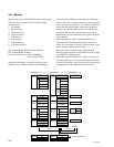
3-5. White Balance Adjustment on
Servicing
3-5-1. Signal Level Adjustment
1. Input the 10 STEP signal to INPUT-A.
2. Warm up the unit at least 10 minutes. Enter the V-
AMP/BRT adjustment mode from the Service mode
as follows :
Service Mode → MENU → DEV. ADJ → P. DRV
→ VAMP/BRT.
3. Measure TP813, TP817, and TP821 on the C board
by osciloscope. Adujust V AMP/BRT so that the
minimum value in all black level is 2.8 V.
4. Input the 95 IRE and 100 IRE STEP signals.
5. Set the unit in G-only mode.
6. Enter the P.DRV on the MENU screen by the DEV.
ADJ.
7. Discriminate the 95 IRE and 100 IRE by the V-
AMP/CONT controls of the P.DRV.
8. Set the unit in R-only mode.
9. Discriminate the 95 IRE and 100 IRE by the V-
AMP/SUB CONT R controls of the P.DRV.
10. Set the unit in B-only mode.
11. Discriminate the 95 IRE and 100 IRE by the V-
AMP/SUB CONT B controls of the P.DRV.
3-5-2. White Balance Adjustment
1) HIGH Mode of INPUT-A
Input the 10 STEP signal to INPUT-A, and observe the
chromaticity of each luminance.
When varying the chromaticity of each luminance,
perform the following adjustments.
1. Input the 100 IRE FLAT FIELD signal to INPUT-A.
2. Measure the chromaticity (x, y).
3. Input the 50 IRE FLAT FIELD signal to INPUT-A.
4. Adjust the chromaticity (x, y) to the values measured
in step 2 by the VAMP/SUB CONT R and B of the
P. DRV.
2) LOW Mode of INPUT-A
1. Input the 80 IRE FLAT FIELD signal to INPUT-A.
2. Set the GAIN G to 60 with the LOW mode of the W/B.
3. Measure the chromaticity (x, y).
4. Input the 25 IRE FLAT FIELD signal to INPUT-A.
5. Adjust the chromaticity (x, y) to the values measured in
step 3 by the BIAS G and B of the LOW mode of the W/B.
6. Repeat above steps 1 to 5 until the chromaticity become
the following values.
x ± 0.002, y ± 0.003 (The x and y are the values
measured in step 3.)
3) HIGH Mode of VIDEO
Switch the input to COMPONENT from INPUT-A by the
SET SETTING of the Menu screen.
Input the 15k COMPONENT 10 STEP signal to INPUT-A,
and observe the chromaticity of each luminance.
When varying the chromaticity of each luminance, perform
the following adjustments.
1. Input the 100 IRE FLAT FIELD signal to INPUT-A.
2. Measure the chromaticity (x, y).
3. Input the 50 IRE FLAT FIELD signal to INPUT-A.
4. Adjust the chromaticity (x, y) to the values measured in
step 2 by the VAMP/SUB CONT R and B of the P. DRV.
4) LOW Mode of VIDEO
1. Input the 80 IRE 15k COMPONENT FLAT FIELD
signal to INPUT-A.
2. Set the GAIN G to 60 with the LOW mode of the W/B.
3. Measure the chromaticity (x, y).
4. Input the 25 IRE FLAT FIELD signal to INPUT-A.
5. Adjust the chromaticity (x, y) to the values measured in
step 3 by the BIAS G and B of the LOW mode of the W/B.
6. Repeat above steps 1 to 5 until the chromaticity become
the following values.
x ± 0.002, y ± 0.003 (The x and y are the values
measured in step 3.)