10
Location and Function of Controls
Chapter 1 Overview
Location: Shows the installation location of the projector
that was set in the SETTING window.
Name: Shows the name of the projector that was set in the
SETTING window.
Operation Timer: Shows the total operating hours of the
projector.
Lamp A/Lamp B: Shows an approximate percentage to
indicate the time used before the recommended time
for replacement of each projection lamp (i.e. 100%
indicates the time for replacement). The indicator on
the left lights when the corresponding lamp turns on.
It does not light when the corresponding lamp turns
off.
Warning Info: Displays an error message if there is any
warning information on the projector. The same
message is displayed in the STATUS MESSAGE
window on the left side of the projector.
d POWER ON/STANDBY (?/1) buttons and
POWER indicator
Click “ON” to turn on the lamp. The indicator lights green.
Clicking “STANDBY” opens the confirmation dialog.
Clicking “OK” makes the projector enter standby mode.
The indicator flashes green. Even in standby mode, the
fans continue to run to reduce internal heat. When the fans
stop running, the indicator lights red.
e FUNCTION 1 to 7 radio buttons
Register the data set or adjusted in the Control Function
Menu windows to these buttons, and recall it later to
project an image with that setting.
The setting items that can be registered are as follows:
• Screen mode and input signal settings in the SCREEN
CONTROL window
• “Input Source” and “Signal Adjust” settings in the
PICTURE CONTROL window
• “Color” settings in the COLOR/FRAME window
• “ELECTRIC V SHIFT FUNCTION”, “SQUEEZE”,
“PROGRESSIVE DISPLAY MODE”, “LAMP
POWER” and “LAMP SELECT” settings, and “LENS
CONTROL” settings when the optional lens equipped
with zoom/focus memory function is installed, in the
INSTALLATION window
For details, see “To register the settings that have been
adjusted” on page 26.
f Window select buttons
Open the window with the items you want to set or adjust.
g Adjustment/setting window
Clicking the window select button switches the window
for the adjustment and setting.
The PICTURE CONTROL, COLOR/FRAME and
INSTALLATION windows can be displayed.
For details on each window, see “Adjustments and
Settings Using the SRX Controller” on page 26.
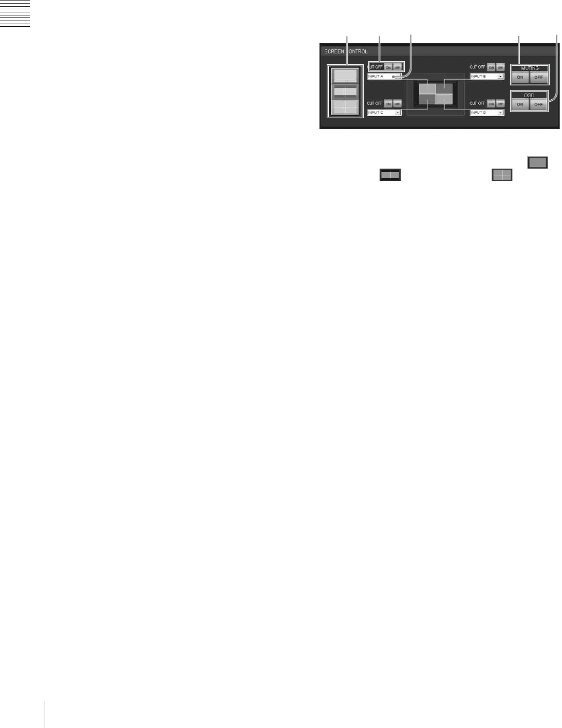
SCREEN CONTROL window
a Screen mode buttons
Select single-, dual- or quad-screen mode. Click for
single-screen, for dual-screen and for quad-
screen mode.
b CUT OFF ON/OFF buttons
Click the “ON” button to cut off the picture momentarily.
Click the “OFF” button to restore the picture.
The SCREEN CONTROL window changes depending on
the screen mode selected with the screen mode button (1).
When dual- or quad-screen mode is selected, the buttons
function independently on each divided screen.
c Input signal select drop-down list box
Selects the input signal you want to project on the screen.
The SCREEN CONTROL window changes depending on
the screen mode selected with the screen mode button (1).
When dual- or quad-screen mode is selected, you can
select the input independently on each divided screen.
INPUT A: Selects the signal input from the connectors on
the pre-installed input board in the INPUT A section.
INPUT B: Selects the signal input from the connectors on
the optional input board installed in the INPUT B
section.
INPUT C: Selects the signal input from the connectors on
the optional input board installed in the INPUT C
section.
INPUT D: Selects the signal input from the connectors on
the optional input board installed in the INPUT D
section.
d MUTING ON/OFF buttons
Clicking the “ON” button cuts off the whole picture on the
screen momentarily. Click the “OFF” button to restore the
picture. Activating the muting function blocks off lamp
light completely by use of a shutter, and displays the black
signal on the whole screen.
e OSD ON/OFF buttons
Click the “OFF” button to eliminate the on-screen display.
Click the “ON” button to display it on the screen.
12 43 5


