


12-2-5 Status (Nibble Mode)................................................................................................................................................................12-2
12-3 Serial RS-232C Interface (D-SUB 25 Pin/D-SUB 9 Pin) ................................................................... 12-3
12-3-1 Specification ...............................................................................................................................................................................12-3
12-3-2 Connector...................................................................................................................................................................................12-3
12-3-3 Communication Protocols........................................................................................................................................................12-5
12-4 USB Interface (B Type)..................................................................................................................... 12-7
12-4-1 Specifications.............................................................................................................................................................................12-7
12-4-2 Connector...................................................................................................................................................................................12-7
12-5 Network Interface (RJ-45)................................................................................................................. 12-7
12-5-1 Specification ...............................................................................................................................................................................12-7
12-5-2 Cable ...........................................................................................................................................................................................12-7
12-5-3 Connector...................................................................................................................................................................................12-7
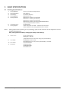
13. BUZZER DRIVER CIRCUIT .................................................................................................................... 13-1
14. DIPSW/MSW (MEMORY SWITCH) SPECIFICATIONS .......................................................................... 14-1
14-1 DIPSW .............................................................................................................................................. 14-1
14-1-1 Memory Board DIP SW1.........................................................................................................................................................14-1
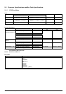
14-1-2 Memory Board DIP SW2.........................................................................................................................................................14-3
14-1-3 RS-232C Interface Board DIPSW 1 ......................................................................................................................................14-3
14-2 MSW (Memory Switch) Specifications .............................................................................................. 14-4
14-2-1 MSW 0 ........................................................................................................................................................................................14-4
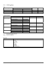
14-2-2 MSW 1 ........................................................................................................................................................................................14-5
14-2-3 MSW 2 ........................................................................................................................................................................................14-7
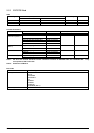
14-2-4 MSW 3 ........................................................................................................................................................................................14-9
14-2-5 MSW 4 .....................................................................................................................................................................................14-13
14-2-6 MSW 8 .....................................................................................................................................................................................14-14
14-2-7 MSW A.....................................................................................................................................................................................14-15
15. OPERATING UNIT SPECIFICATIONS ................................................................................................... 15-1
15-1 Operation Panel Specifications......................................................................................................... 15-1
15-2 LED Specifications............................................................................................................................ 15-2
15-3 Error Specifications........................................................................................................................... 15-3
15-3-1 Auto-recovery Error...................................................................................................................................................................15-3
15-3-2 Recoverable Error.....................................................................................................................................................................15-3
15-3-3 Non-recoverable Error..............................................................................................................................................................15-3
15-4 Sensor Adjustment Mode.................................................................................................................. 15-4
15-4-1 PE/BM Common Sensor Adjustment Mode........................................................................................................................15-4
15-4-2 NE Sensor Adjustment Mode.................................................................................................................................................15-4
15-4-3 Stack Sensor Adjustment Mode.............................................................................................................................................15-4
16. COMMAND SPECIFICATIONS............................................................................................................... 16-1
16-1 STAR Line Mode............................................................................................................................... 16-1
16-2 STAR Page Mode ............................................................................................................................. 16-2
16-3 ESC/POS Mode ................................................................................................................................ 16-3