


12-3-3 Communication Protocols
1) General description of operations in the DTR mode
This mode is set when the DIPSW #1-3 are turned ON. (The ex-factory setting)
This mode performs communication while handshaking with the DTR signals. In the operations to receive printer data, this
mode controls the DTR signals by confirming the BUSY signal. A SPACE indicates that the printer is ready to receive
data; conversely, a “mark” indicates that the printer cannot receive data.
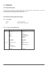
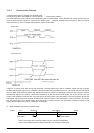
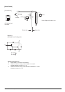
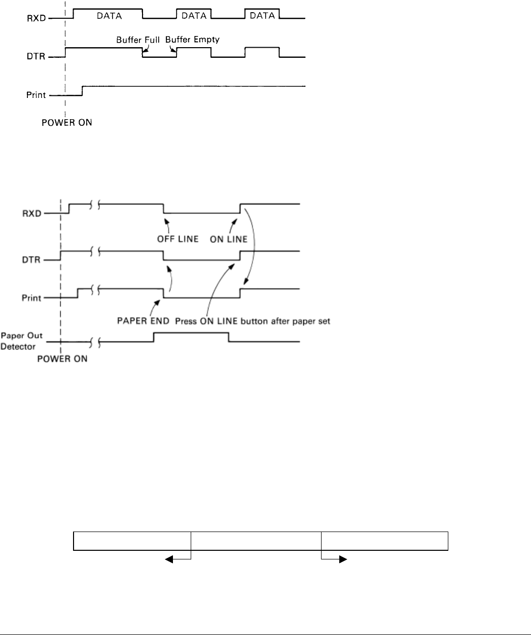
<When online>
<When paper is out>
If there is no printer error after turning ON the power, the DTR signal line is set to a SPACE. When the host computer
confirms that the DTR signal line is a SPACE, it sends the data text to the RXD signal line. The printer sets the DTR signal
line to a “Mark” after the empty area of the data buffer reaches a maximum of 256 bytes. When the host computer confirms
that the DTR signal line is a Mark, it stops the transmission of data text to the printer buffer, but at this point as well, the
printer is still capable of receiving data, up to the amount of empty space in the data buffer. If the host computer ignores the
DTR signal and transmits data, all data exceeding the amount of space in the data buffer is simply discarded. The printer
sets the DTR signal line to SPACE again when the amount of empty space in the data buffer increased because of the
printing and the data in the buffer is a maximum of 256 bytes.
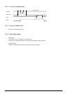
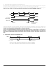
2) Buffer full/Buffer full cancel in the DTR mode
Buffer Full Near Full Near Empty Empty
Empty Area 256 Bytes Reception Data 256 Bytes
DTR “Mark” DTR “Space”
DTR is set to mark at the point the empty area is a maximum of 256 bytes.
DTR is set to SPACE when the data in the buffer is a minimum of 256 bytes.
TSP1000 Series Product Specifications 12-5