


15-4
15-4-1
15-4-2
15-4-3
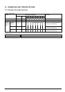
Sensor Adjustment Mode
This mode adjusts the sensitivity of the sensor by adjusting the variable resistor on the PCB.
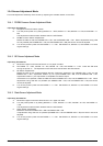
PE/BM Common Sensor Adjustment Mode
<Operating Procedures>
A. Set paper into the PE sensor portion.
B. Turn the printer power on by setting DIPSW 1-4 = OFF, DIPSW 1-5 = ON, DIPSW 1-6 = ON, and DIPSW 1-7 =
ON.
The adjustment mode has been entered when the LED flashes.
C. PE/BM Common Sensor Adjustments
Rotate the VR2 so that the POWER LED = ON, and the ERROR LED = ON. When adjustments using VR2
are not possible (the POWER LED = ON, and the ERROR LED = ON) the sensor cannot be adjusted.
D. Turn off the printer’s power and set DIPSW 1 – 4 = ON. Set DIPSW 1-5, DIPSW 1-6, and DIPSW 1-7 to their
original settings.
NE Sensor Adjustment Mode
<Operating Procedures>
A. Remove the paper so that the NE sensor is in a paper out state.
B. Set DIPSW 1-4 = OFF, DIPSW 1-5 = ON, DIPSW 1-6 = ON, and DIPSW 1-7 = ON. Press the SW while
turning the printer on. The adjustment mode has been entered when the LED flashes.
C. NE Sensor Adjustments
Rotate the VR6 in the counterclockwise direction (maximum sensitivity); (the POWER LED = ON, and the
ERROR LED = OFF: Adjustment Position 2); Or if (the POWER LED = ON, and the ERROR LED = ON:
Adjustment Position 1), the adjustment is completed: Proceed to step D.
If the above is not possible, rotate the VR6 so that the POWER LED = ON, and the ERROR LED = ON. When
adjustments using VR6 are not possible (the POWER LED = ON, and the ERROR LED = ON) the sensor
cannot be adjusted.
D. Turn off the printer’s power and set DIPSW 1 – 4 = ON. Set DIPSW 1-5, DIPSW 1-6, and DIPSW 1-7 to their
original settings.
Stack Sensor Adjustment Mode
<Operating Procedures>
A. Remove the paper so that the stack sensor is in a paper out state.
B. Turn the printer power on by setting DIPSW 1-4 = OFF, DIPSW 1-5 = OFF, DIPSW 1-6 = ON, and DIPSW 1-7
= ON.
The adjustment mode has been entered when the LED flashes.
C. Stack Sensor Adjustments
Rotate the VR5 until POWER LED = ON and ERROR LED = ON.
If adjustments using VR5 are not possible (POWER LED = ON and ERROR LED = ON) the sensor cannot be
adjusted.
D. Turn off the printer’s power and set DIPSW 1 – 4 = ON. Set DIPSW 1-5, DIPSW 1-6, and DIPSW 1-7 to their
original settings.
TSP1000 Series Product Specifications 15-4