


12-3
12-3-1
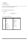
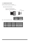
12-3-2 Connector
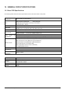
Serial RS-232C Interface (D-SUB 25 Pin/D-SUB 9 Pin)
Specification
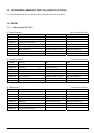
Standard: RS-232C
Transmission method: Start-Stop synchronization method
Baud Rate: 4800, 9600, 19200, 38400 bps
(Set by DIP switches)
Data length: 7 or 8 bits (Set by DIP switches)
Parity: Parity or not (Set by DIP switches)
Parity bit: Odd or even (Set by DIP switches)
Stop bit: 1 bit (Fixed)
Signal polarity: Mark = Logic 1 (-3 V to -15 V)
Space = Logic 0 (+3 V to +15 V)
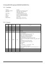
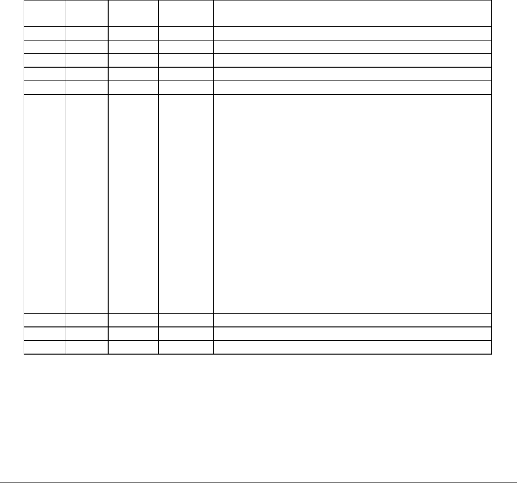
Pin No
25 Pins
Pin No
9 Pins
Signal
Name
Direction Functions
1 - FG - Frame ground
2 3 TXD OUT Transmission Data
3 2 RXD IN Reception Data
4 7 RTS OUT Always SPACE (Reception Possible)
5 - N.C - Not Used
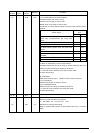
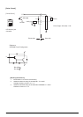
6 6 DSR IN
1) DIP Switch 1-7 (on I/F Card) = OFF
A. ESC/POS Mode
Indicates whether the host can receive data.
SPACE: Host is ready to receive data
MARK: Host is not ready to receive data
a) DTR/DSR Communications Mode
Checks that status of this signal and sends data.
(However, this excludes data transmission using <DEL><EOT>,
<GS>a)
b) XON/XOFF Communications Mode
Does not check the status of this signal.
B. STAR Mode
Not Used
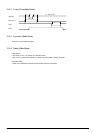
2) DIP Switch 1-7 (on I/F Card) = ON
Becomes an external reset signal.
Reset is applied when there is a mark status with over 1 ms
pulse width.
- 8 CTS IN Same as DSR
7 5 SG - Signal ground
8-19 1 N.C - Not Used
TSP1000 Series Product Specifications 12-3