


Chapter 2: Installation
2-15
FAN2
FAN3
FAN1
JI2C1
JI2C2
JWOR
FAN4
JP3
JWD
JLED
Battery
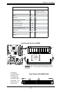
DIMM1A
DIMM2A
DIMM1B
DIMM2B
I-SATA4
I-SATA5
WO
Speaker
COM1
KB/MOUSE
CPU Fan
VGA
USB
3/4/5/6
USB 1/2
LAN
Fan5
Audio
4-Pin PWR
Processor
Slot7 PCI-E x1
Slot6 PCI-E x16
Slot5 PCI-E x4
Slot4 PCI-33MHz
JP5
Slot3 PCI-33MHz
JP2
Slot2 PCI-33MHz
Buzzer
SPKR1
Slot1 PCI-33MHz
C2SBA
WOL
IDE#2
IDE#1
FP USB 7/8
FP USB 9/10
I-SATA0
I-SATA1
JL1
LE1
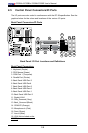
Front Panel CTRL
Intel G33
North Bridge
South Bridge
Intel ICH9(R)
24-pin ATX PWR
Audio CTRL
CD-IN
COM2
Front Audio
W83627DHG
Floppy
S I/O
IDE CTRL
ITE 8212
Audio Enabled
Front-Access USB 11Front-Access USB 12
I-SATA2
I-SATA3
JPUSB1
JKB
JPUSB2
GLAN CTRL
JPL1
JBT1
BIOS
Parallel Port
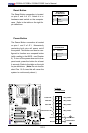
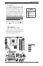
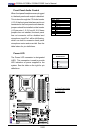
Fan Headers
The C2SBA+II/C2SBA+/C2SBA/C2SBE
has ve chassis fan headers (Fan 1 to Fan
5). Fan 1 is the CPU Fan. Fan 2 to Fan
5 are system/chassis fans. (Note: Pins
1-3 of a 4-pin fan headers are backward
compatible with the traditional 3-pin fans.)
See the table on the right for pin denitions.
The onboard fan speeds are controlled by
Thermal Management via BIOS Hardware
Monitoring in the Advanced Setting. (Note:
Default: Disabled. When using Thermal
Management settings, please use all 3-pin
fans or all 4-pin fans on the motherboard.)
C
A
A. Fan 1 (CPU Fan)
B. Fan 2
C. Fan 3
D. Fan 4
E. Fan 5
F. VGA
Fan Header
PinDenitions
Pin# Denition
1 Ground
2 +12V
3 Tachometer
4 PWR Modulation
D
E
F
B
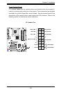
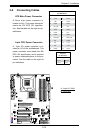
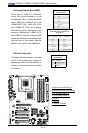
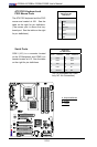
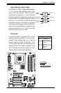
VGA Connector
(Not available on the C2SBE)
A VGA connector (JG1) is located next to the
USB ports on the IO backplane. Refer to the
board layout below for the location.