


Chapter 2: Installation
2-17
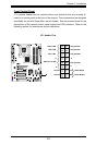
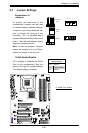
FAN2
FAN3
FAN1
JI2C1
JI2C2
JWOR
FAN4
JP3
JWD
JLED
Battery
DIMM1A
DIMM2A
DIMM1B
DIMM2B
I-SATA4
I-SATA5
WO
Speaker
COM1
KB/MOUSE
CPU Fan
VGA
USB
3/4/5/6
USB 1/2
LAN
Fan5
Audio
4-Pin PWR
Processor
Slot7 PCI-E x1
Slot6 PCI-E x16
Slot5 PCI-E x4
Slot4 PCI-33MHz
JP5
Slot3 PCI-33MHz
JP2
Slot2 PCI-33MHz
Buzzer
SPKR1
Slot1 PCI-33MHz
C2SBA
WOL
IDE#2
IDE#1
FP USB 7/8
FP USB 9/10
I-SATA0
I-SATA1
JL1
LE1
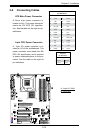
Front Panel CTRL
Intel G33
North Bridge
South Bridge
Intel ICH9(R)
24-pin ATX PWR
Audio CTRL
CD-IN
COM2
Front Audio
W83627DHG
Floppy
S I/O
IDE CTRL
ITE 8212
Audio Enabled
Front-Access USB 11Front-Access USB 12
I-SATA2
I-SATA3
JPUSB1
JKB
JPUSB2
GLAN CTRL
JPL1
JBT1
BIOS
Parallel Port
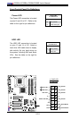
A. WOR
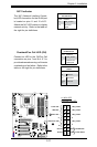
B. WOL
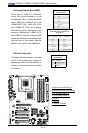
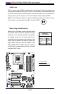
Wake-On-Ring
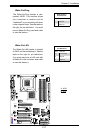
The Wake-On-Ring header is des-
ignated JWOR. This function allows
your computer to receive and be
"awakened" by an incoming call when
in the suspend state. See the table on
the right for pin denitions. You must
have a Wake-On-Ring card and cable
to use this feature.
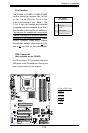
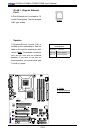
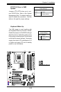
Wake-On-LAN
The Wake-On-LAN header is located
at JWOL on the motherboard. See the
table on the right for pin denitions.
(You must also have a LAN card with
a Wake-On-LAN connector and cable
to use this feature.)
Wake-On-Ring
PinDenitions
Pin# Denition
1 Ground
2 Wake-up
Wake-On-LAN
PinDenitions
Pin# Denition
1 +5V Standby
2 Ground
3 Wake-up
A
B