


C2SBA+II/C2SBA+/C2SBA/C2SBE User’s Manual
iv
Table of Contents
About This Manual ...................................................................................................... iii
Manual Organization ....................................................................................................iii
Conventions Used in the Manual ..................................................................................iii
Chapter 1: Introduction
1-1 Overview ......................................................................................................... 1-1
Checklist ..................................................................................................... 1-1
Contacting Super Micro .............................................................................. 1-2
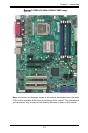
C2SBA+II/C2SBA+/C2SBA/C2SBE Image ............................... 1-3
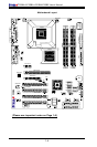
C2SBA+II/C2SBA+/C2SBA/C2SBE Layout ................................ 1-4
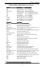
C2SBA+II/C2SBA+/C2SBA/C2SBE Quick Reference................. 1-5
Motherboard Features .............................................................................. 1-7
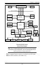
Intel G33/P35 Chipset: System Block Diagram ......................................... 1-9
1-2 Chipset Overview ......................................................................................... 1-10
1-3 Recovery from AC Power Loss .................................................................... 1-11
1-4 PC Health Monitoring ................................................................................... 1-11
1-5 ACPI Features .................................................................................................1-11
1-6 Power Supply ............................................................................................... 1-12
1-7 Versatile Media Capabilities ........................................................................... 1-13
1-8 Super I/O ...................................................................................................... 1-13
Chapter 2: Installation
2-1 Static-Sensitive Devices ................................................................................. 2-1
2-2 Motherboard Installation .................................................................................. 2-1
2-3 Processor and Heatsink Installation ............................................................... 2-2
2-4 Installing DDR2 Memory ................................................................................ 2-6
2-5 Control Panel Connectors/IO Ports ................................................................. 2-8
Back Panel Connectors/IO Ports ...................................................................... 2-8
Front Control Panel .......................................................................................... 2-9
Front Control Panel Pin Denitions ................................................................ 2-10
PWR LED ...............................................................................................2-10
HDD LED ................................................................................................. 2-10
NIC1 LED Indicators .............................................................................. 2-11
OH/Fan Fail LED ......................................................................................2-11
Reset Button ............................................................................................ 2-12
PWR Button ............................................................................................. 2-12
2-6 Connecting Cables ....................................................................................... 2-13
ATX/Auxiliary Power Connectors ........................................................... 2-13
Universal Serial Bus (USB) ..................................................................... 2-14