


Chapter 2: Installation
2-19
FAN2
FAN3
FAN1
JI2C1
JI2C2
JWOR
FAN4
JP3
JWD
JLED
Battery
DIMM1A
DIMM2A
DIMM1B
DIMM2B
I-SATA4
I-SATA5
WO
Speaker
COM1
KB/MOUSE
CPU Fan
VGA
USB
3/4/5/6
USB 1/2
LAN
Fan5
Audio
4-Pin PWR
Processor
Slot7 PCI-E x1
Slot6 PCI-E x16
Slot5 PCI-E x4
Slot4 PCI-33MHz
JP5
Slot3 PCI-33MHz
JP2
Slot2 PCI-33MHz
Buzzer
SPKR1
Slot1 PCI-33MHz
C2SBA
WOL
IDE#2
IDE#1
FP USB 7/8
FP USB 9/10
I-SATA0
I-SATA1
JL1
LE1
Front Panel CTRL
Intel G33
North Bridge
South Bridge
Intel ICH9(R)
24-pin ATX PWR
Audio CTRL
CD-IN
COM2
Front Audio
W83627DHG
Floppy
S I/O
IDE CTRL
ITE 8212
Audio Enabled
Front-Access USB 11Front-Access USB 12
I-SATA2
I-SATA3
JPUSB1
JKB
JPUSB2
GLAN CTRL
JPL1
JBT1
BIOS
Parallel Port
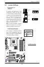
A
B
A. HD Audio
B. CD-In
C. Front Panel Audio
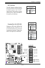
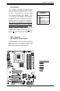
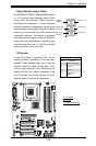
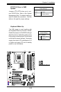
HighDenitionAudio(HDA)
The C2SBA+II/C2SBA+/C2SBA/C2SBE features
a 7.1+2 Channel High Denition Audio (HDA)
(J46) codec that provides 10DAC channels,
simultaneously supporting 7.1 sound playback
and two channels of independent stereo sound
output (multiple streaming) through the front panel
stereo out for front L&R, rear L&R, center and
subwoofer speakers. This feature is activated
with the Advanced software in the CD-ROM that
came with your motherboard. Sound is then
output through the Line In, Line Out and MIC
jacks (See at the picture at right).
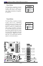
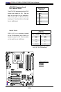
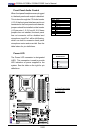
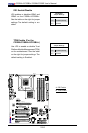
CD1PinDenition
Pin# Denition
1 Left Stereo Signal
2 Ground
3 Ground
4 Right Stereo
Signal
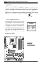
C
Grey: Side
Surround
Black: Back
Surround
Orange:
CEN/LFE
Pink: Mic-In
Green:Front
Blue: Line-In
CD Header
A 4-pin CD header is located at CD1, and an
Auxiliary header is located at J12 on the moth-
erboard. These headers allow you to use the
onboard sound for audio CD playback. Con-
nect an audio cable from your CD drive to the
header that ts your cable's connector. Only
one CD header can be used at any one time.
See the tables at right for pin denitions.