Operating Basics
4
P6434 Probe Instructions
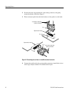
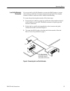
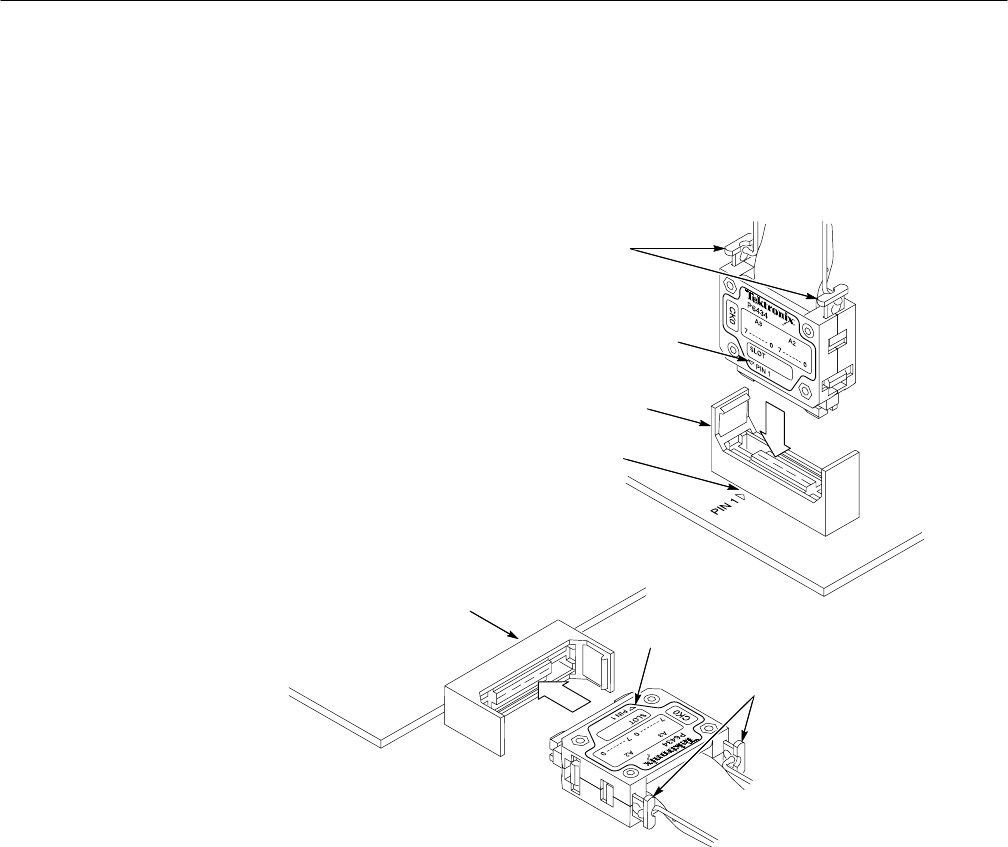
2. Position the probe tip perpendicular to the mating connector, and gently
connect the probe as shown in Figure 3.
3. When connected, push down the latch releases on the probe to set the latch.
Optional latch housing
Pin 1
Push down to latch after
probe is connected
Push down to latch after
probe is connected
Optional latch housing
Pin 1
Pin 1
Figure 3: Connecting to a surface- or straddle-mounted connector
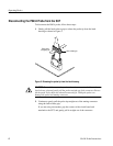
4. Connect the module end to the corresponding connector (match label colors)
on the logic analyzer module. The module end is keyed.


