Designing an Interface Between a P6434 Probe and a SUT
10
P6434 Probe Instructions
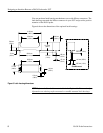
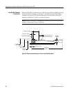
When placing Mictor connectors in your SUT for use with an extender, you need
to keep one inch of clear space on the pin 1 side from the center of the Mictor
connector in your SUT. The vertical clearance for the one inch of clear space
under the extender is 0.2 inches, as shown in Figure 8.
NOTE. Be sure to orient pin 1 on the Mictor connector in your SUT to direct the
extender off the board as shown in Figure 4.
107.95 mm
(4.250 in)
10.16 mm
(.400 in)
5.08 mm
(.200 in)
9.90 mm
(.390 in)
12.19 mm
(.480 in)
2.54 mm (.100 in)
9.52 mm (.375 in) min.
bend radius of cable
Optional latch housing
25.40 mm (1.000 in)
4.953 mm (.195 in)
Figure 8: Side view and dimensions of the Low-Profile Extender
Low-Profile Extender
Connection


