P6434 Probe Instructions
7
Designing an Interface Between a P6434 Probe and a SUT
This section provides you with some guidelines for designing your own P6434
probe interface on the SUT. The guidelines contain information on the following
topics:
H Mictor connectors
H Dimensions and placement of connectors
H Mechanical layout and pinout of connectors
H Probe channel assignments
H Loading and equivalent circuits
Mictor Connectors and Latch Housings
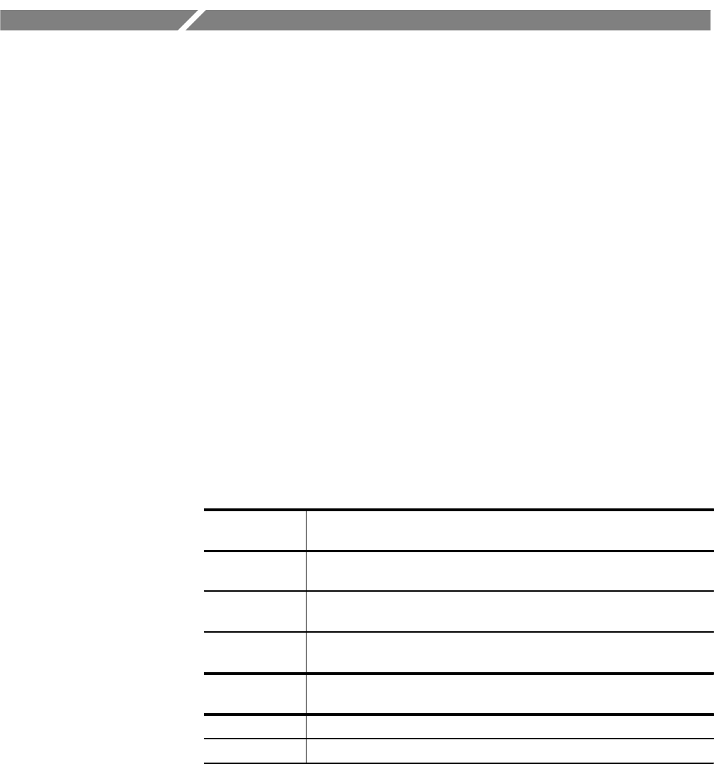
The P6434 probe contains a 38-pin Mictor connector. Table 2 lists Mictor
connectors you can purchase from AMP, Inc., that are compatible with the probe,
as well as the compatible latch housings that are available from Tektronix.
Table 2: Compatible Mictor connectors
AMP, Inc.
part number
Description
767054-1* Palladium-nickel plated, 0.054 inch long ground pins, surface mount
connector (vertical receptacles)
2-767004-2 30 microinches gold plating, 0.054 inch long ground pins, surface mount
connector (vertical receptacles)
767044-1* Palladium-nickel plated, straddle mount connector (0.062 inch circuit board
thickness, right-angle receptacles)
Tektronix
part number
Description
105-1088-00 Latch housing; straddle mount (0.062 inch circuit board thickness)
105-1089-00 Latch housing; surface mount
* Recommended
You can contact AMP, Inc. for more detailed information on the Mictor
connectors. For the address, refer to the Replaceable Parts section.


