Designing an Interface Between a P6434 Probe and a SUT
14
P6434 Probe Instructions
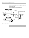
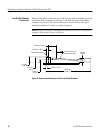
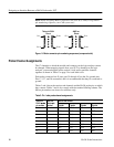
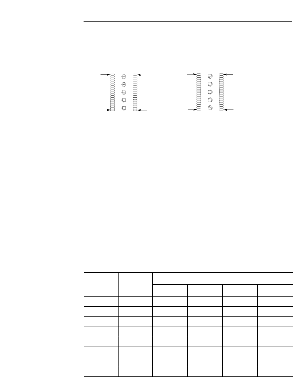
NOTE. When designing Mictor connectors into your SUT, always verify which
pin-numbering sequence your CAD system uses.
Pin 1
Pin 19
Pin 38
Pin 20
Pin 2
Pin 38
Pin 1
Pin 37
Tektronix P6434
Pinout
AMP, Inc.
Pinout
Figure 11: Mictor connector pin numbering sequences (component side)
Probe Channel Assignments
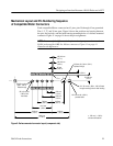
The 17 channels to which the module end connects on the logic analyzer cannot
be changed. When mapping signals from your SUT to channels on the logic
analyzer, you must keep the probe section, clock, and/or qualifier channels
together as shown in Table 1 on page 2 for each label color.
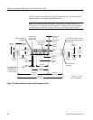
Each probe connector has 43 pins; pins 39 through 43 are the five ground pins.
Pins 1, 2, 37, and 38 are unused, and it is recommended that they be connected to
ground.
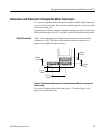
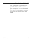
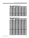
Tables 3 and 4 show the sections and channels and the P6434 probe pins to which
they connect. Tables 3 and 4 also comply with the standard labeling scheme. The
Mictor pin numbers are shown for reference only.
Table 3: Pin 1 side probe channel assignments
Tek
t
r
on
i
x
pr be
A
MP
,
Inc
.
irpi
Section and channel
P6434
pr
o
be
pin number
M
i
cto
r
pi
n
number
A probe C probe D probe E probe
3 5 CLK:0 CLK:3 Q0 Q3
4 7 A3:7 C3:7 D3:7 E3:7
5 9 A3:6 C3:6 D3:6 E3:6
6 11 A3:5 C3:5 D3:5 E3:5
7 13 A3:4 C3:4 D3:4 E3:4
8 15 A3:3 C3:3 D3:3 E3:3
9 17 A3:2 C3:2 D3:2 E3:2
10 19 A3:1 C3:1 D3:1 E3:1


