


www.ti.com
Peripheral Architecture
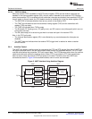
2.6.3 FIFO Modes
The following two modes can be used for servicing the receiver and transmitter FIFOs:
• FIFO interrupt mode. The FIFO is enabled and the associated interrupts are enabled. Interrupts are
sent to the CPU to indicate when specific events occur.
• FIFO poll mode. The FIFO is enabled but the associated interrupts are disabled. The CPU polls status
bits to detect specific events.
Because the receiver FIFO and the transmitter FIFO are controlled separately, either one or both can be
placed into the interrupt mode or the poll mode.
2.6.3.1 FIFO Interrupt Mode
When the receiver FIFO is enabled in the FIFO control register (FCR) and the receiver interrupts are
enabled in the interrupt enable register (IER), the interrupt mode is selected for the receiver FIFO. The
following are important points about the receiver interrupts:
• The receiver data-ready interrupt is issued to the CPU when the FIFO has reached the trigger level
that is programmed in FCR. It is cleared when the CPU or the DMA controller reads enough characters
from the FIFO such that the FIFO drops below its programmed trigger level.
• The receiver line status interrupt is generated in response to an overrun error, a parity error, a framing
error, or a break. This interrupt has higher priority than the receiver data-ready interrupt. For details,
see Section 2.9.
• The data-ready (DR) bit in the line status register (LSR) indicates the presence or absence of
characters in the receiver FIFO. The DR bit is set when a character is transferred from the receiver
shift register (RSR) to the empty receiver FIFO. The DR bit remains set until the FIFO is empty again.
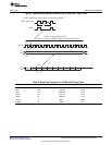
• A receiver time-out interrupt occurs if all of the following conditions exist:
– At least one character is in the FIFO,
– The most recent character was received more than four continuous character times ago. A
character time is the time allotted for 1 START bit, n data bits, 1 PARITY bit, and 1 STOP bit,
where n depends on the word length selected with the WLS bits in the line control register (LCR).
See Table 4.
– The most recent read of the FIFO has occurred more than four continuous character times before.
• Character times are calculated by using the baud rate.
• When a receiver time-out interrupt has occurred, it is cleared and the time-out timer is cleared when
the CPU or the EDMA controller reads one character from the receiver FIFO. The interrupt is also
cleared if a new character is received in the FIFO or if the URRST bit is cleared in the power and
emulation management register (PWREMU_MGMT).
• If a receiver time-out interrupt has not occurred, the time-out timer is cleared after a new character is
received or after the CPU or EDMA reads the receiver FIFO.
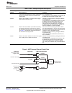
When the transmitter FIFO is enabled in FCR and the transmitter holding register empty interrupt is
enabled in IER, the interrupt mode is selected for the transmitter FIFO. The transmitter holding register
empty interrupt occurs when the transmitter FIFO is empty. It is cleared when the transmitter hold register
(THR) is loaded (1 to 16 characters may be written to the transmitter FIFO while servicing this interrupt).
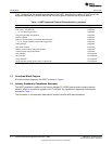
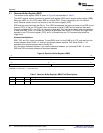
Table 4. Character Time for Word Lengths
Word Length (n) Character Time Four Character Times
5 Time for 8 bits Time for 32 bits
6 Time for 9 bits Time for 36 bits
7 Time for 10 bits Time for 40 bits
8 Time for 11 bits Time for 44 bits
15
SPRU997C–December 2009 Universal Asynchronous Receiver/Transmitter (UART)
Submit Documentation Feedback
Copyright © 2009, Texas Instruments Incorporated