


Introduction
www.ti.com
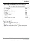
Table 1 summarizes the capabilities supported on the UART. Note that the number of UARTs and their
supported features vary on each device, see the device-specific data manual for more details.
Table 1. UART Supported Features/Characteristics by Instance
Feature Support
5, 6, 7 or 8-bit characters Supported
Even, odd, or no PARITY bit Supported
1, 1.5, or 2 STOP bit generation Supported
Line break generation and detection Supported
Internal loop back Supported
DMA sync events for both received and transmitted data Supported
1, 4, 8, or 14 byte selectable receiver FIFO trigger level Supported
Polling/Interrupt Supported
Max speed 128 kbps Supported
Modem control functions using CTS and RTS Supported
(1)
Autoflow control using CTS and RTS Supported
(1)
DTR and DSR Not supported
Ring indication Not supported
Carrier detection Not supported
Single-character transfer mode (mode 0) in DMA mode Not supported
(1)
Not supported on all UARTs. See the device-specific data manual for supported features.
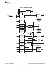
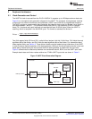
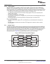
1.3 Functional Block Diagram
A functional block diagram of the UART is shown in Figure 1.
1.4 Industry Standard(s) Compliance Statement
The UART peripheral is based on the industry standard TL16C550 asynchronous communications
element, which is a functional upgrade of the TL16C450. Any deviations in supported functions are
indicated in Table 1.
The information in this document assumes the reader is familiar with these standards.
8
Universal Asynchronous Receiver/Transmitter (UART) SPRU997C–December 2009
Submit Documentation Feedback
Copyright © 2009, Texas Instruments Incorporated