


Registers
www.ti.com
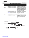
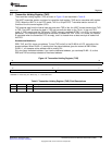
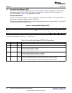
3.3 Interrupt Enable Register (IER)
The interrupt enable register (IER) is used to individually enable or disable each type of interrupt request
that can be generated by the UART. Each interrupt request that is enabled in IER is forwarded to the
CPU. IER is shown in Figure 11 and described in Table 9.
Access considerations:
IER and DLH share one address. To read or modify IER, write 0 to the DLAB bit in LCR. When DLAB = 1,
all accesses at the shared address read or modify DLH.
DLH also has a dedicated address. If you use the dedicated address, you can keep DLAB = 0, so that IER
is always selected at the shared address.
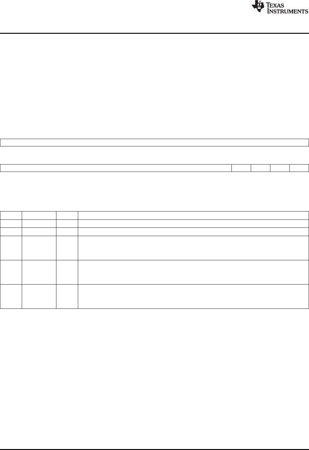
Figure 11. Interrupt Enable Register (IER)
31 16
Reserved
R-0
15 4 3 2 1 0
Reserved Rsvd ELSI ETBEI ERBI
R-0 R/W-0 R/W-0 R/W-0 R/W-0
LEGEND: R/W = Read/Write; R = Read only; -n = value after reset
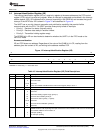
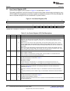
Table 9. Interrupt Enable Register (IER) Field Descriptions
Bit Field Value Description
31-4 Reserved 0 Reserved
3 Reserved 0 Reserved. This bit must always be written with a 0.
2 ELSI Receiver line status interrupt enable.
0 Receiver line status interrupt is disabled.
1 Receiver line status interrupt is enabled.
1 ETBEI Transmitter holding register empty interrupt enable.
0 Transmitter holding register empty interrupt is disabled.
1 Transmitter holding register empty interrupt is enabled.
0 ERBI Receiver data available interrupt and character timeout indication interrupt enable.
0 Receiver data available interrupt and character timeout indication interrupt is disabled.
1 Receiver data available interrupt and character timeout indication interrupt is enabled.
24
Universal Asynchronous Receiver/Transmitter (UART) SPRU997C–December 2009
Submit Documentation Feedback
Copyright © 2009, Texas Instruments Incorporated