


rts
Receiver
FIFO
D[7:0]
UART
Serial to
Parallel
Flow
Control
Transmitter
FIFO
Parallel to
Serial
Flow
Control
Parallel to
Serial
Flow
Control
Serial to
Parallel
Flow
Control
UART
Transmitter
FIFO
Receiver
FIFO
D[7:0]
DMP Off-chip
tx
cts
rx
rx
rts
tx
cts
Peripheral Architecture
www.ti.com
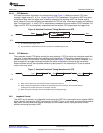
2.6.3.2 FIFO Poll Mode
When the receiver FIFO is enabled in the FIFO control register (FCR) and the receiver interrupts are
disabled in the interrupt enable register (IER), the poll mode is selected for the receiver FIFO. Similarly,
when the transmitter FIFO is enabled and the transmitter interrupts are disabled, the transmitted FIFO is in
the poll mode. In the poll mode, the CPU detects events by checking bits in the line status register (LSR):
• The RXFIFOE bit indicates whether there are any errors in the receiver FIFO.
• The TEMT bit indicates that both the transmitter holding register (THR) and the transmitter shift
register (TSR) are empty.
• The THRE bit indicates when THR is empty.
• The BI (break), FE (framing error), PE (parity error), and OE (overrun error) bits specify which error or
errors have occurred.
• The DR (data-ready) bit is set as long as there is at least one byte in the receiver FIFO.
Also, in the FIFO poll mode:
• The interrupt identification register (IIR) is not affected by any events because the interrupts are
disabled.
• The UART does not indicate when the receiver FIFO trigger level is reached or when a receiver
time-out occurs.
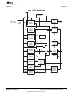
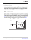
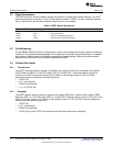
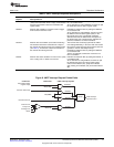
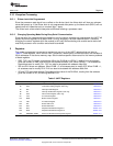
2.6.4 Autoflow Control
The UART can employ autoflow control by connecting the CTS and RTS signals. Note that all UARTs do
not support autoflow control, see the device-specific data manual for supported features. The CTS input
must be active before the transmitter FIFO can transmit data. The RTS becomes active when the receiver
needs more data and notifies the sending device. When RTS is connected to CTS, data transmission
does not occur unless the receiver FIFO has space for the data. Therefore, when two UARTs are
connected as shown in Figure 5 with autoflow enabled, overrun errors are eliminated.
Figure 5. UART Interface Using Autoflow Diagram
16
Universal Asynchronous Receiver/Transmitter (UART) SPRU997C–December 2009
Submit Documentation Feedback
Copyright © 2009, Texas Instruments Incorporated