


User's Guide
SPRU997C–December 2009
Universal Asynchronous Receiver/Transmitter (UART)
1 Introduction
This document describes the universal asynchronous receiver/transmitter (UART) peripheral in the
TMS320DM643x Digital Media Processor (DMP) .
1.1 Purpose of the Peripheral
The UART peripheral is based on the industry standard TL16C550 asynchronous communications
element, which in turn is a functional upgrade of the TL16C450. Functionally similar to the TL16C450 on
power up (single character or TL16C450 mode), the UART can be placed in an alternate FIFO
(TL16C550) mode. This relieves the CPU of excessive software overhead by buffering received and
transmitted characters. The receiver and transmitter FIFOs store up to 16 bytes including three additional
bits of error status per byte for the receiver FIFO.
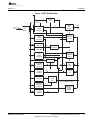
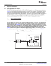
The UART performs serial-to-parallel conversions on data received from a peripheral device and
parallel-to-serial conversion on data received from the CPU. The CPU can read the UART status at any
time. The UART includes control capability and a processor interrupt system that can be tailored to
minimize software management of the communications link.
The UART includes a programmable baud generator capable of dividing the UART input clock by divisors
from 1 to 65 535 and producing a 16 × reference clock for the internal transmitter and receiver logic. For
detailed timing and electrical specifications for the UART, see the device specific data manual.
1.2 Features
The UART peripheral has the following features:
• Programmable baud rates up to 128 kbps (frequency pre-scale values from 1 to 65535)
• Fully programmable serial interface characteristics:
– 5, 6, 7, or 8-bit characters
– Even, odd, or no PARITY bit generation and detection
– 1, 1.5, or 2 STOP bit generation
• 16-byte depth transmitter and receiver FIFOs:
– The UART can be operated with or without the FIFOs
– 1, 4, 8, or 14 byte selectable receiver FIFO trigger level for autoflow control and DMA
• DMA signaling capability for both received and transmitted data
• CPU interrupt capability for both received and transmitted data
• Operates in little-endian mode
• False START bit detection
• Line break generation and detection
• Internal diagnostic capabilities:
– Loopback controls for communications link fault isolation
– Break, parity, overrun, and framing error simulation
• Programmable autoflow control using CTS and RTS signals (not supported on all UARTs. See the
device-specific data manual for supported features.)
• Modem control functions using CTS and RTS signals (not supported on all UARTs. See the
device-specific data manual for supported features.)
7
SPRU997C–December 2009 Universal Asynchronous Receiver/Transmitter (UART)
Submit Documentation Feedback
Copyright © 2009, Texas Instruments Incorporated