Registers
www.ti.com
3.1 Receiver Buffer Register (RBR)
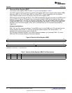
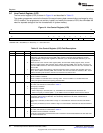
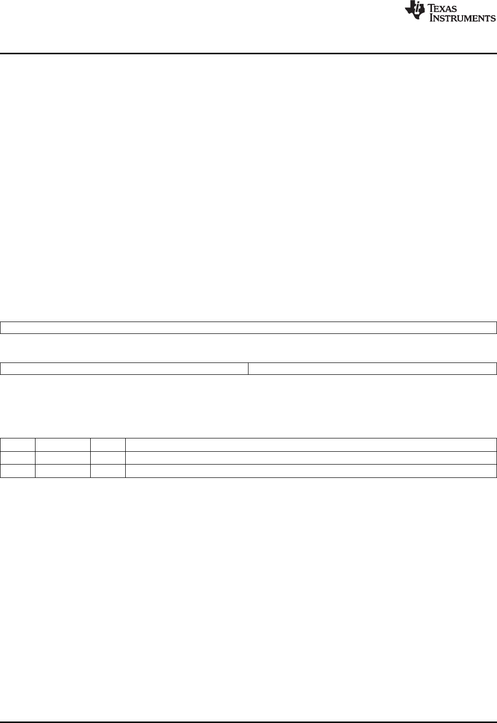
The receiver buffer register (RBR) is shown in Figure 9 and described in Table 7.
The UART receiver section consists of a receiver shift register (RSR) and a receiver buffer register (RBR).
When the UART is in the FIFO mode, RBR is a 16-byte FIFO. Timing is supplied by the 16x receiver
clock. Receiver section control is a function of the line control register (LCR).
RSR receives serial data from the RX pin. Then RSR concatenates the data and moves it into RBR (or the
receiver FIFO). In the non-FIFO mode, when a character is placed in RBR and the receiver data-ready
interrupt is enabled (DR = 1 in IER), an interrupt is generated. This interrupt is cleared when the character
is read from RBR. In the FIFO mode, the interrupt is generated when the FIFO is filled to the trigger level
selected in the FIFO control register (FCR), and it is cleared when the FIFO contents drop below the
trigger level.
Access considerations:
RBR, THR, and DLL share one address. To read RBR, write 0 to the DLAB bit in LCR, and read from the
shared address. When DLAB = 0, writing to the shared address modifies THR. When DLAB = 1, all
accesses at the shared address read or modify DLL.
DLL also has a dedicated address. If you use the dedicated address, you can keep DLAB = 0, so that
RBR and THR are always selected at the shared address.
Figure 9. Receiver Buffer Register (RBR)
31 16
Reserved
R-0
15 8 7 0
Reserved DATA
R-0 R-0
LEGEND: R = Read only; -n = value after reset
Table 7. Receiver Buffer Register (RBR) Field Descriptions
Bit Field Value Description
31-8 Reserved 0 Reserved
7-0 DATA 0-FFh Received data
22
Universal Asynchronous Receiver/Transmitter (UART) SPRU997C–December 2009
Submit Documentation Feedback
Copyright © 2009, Texas Instruments Incorporated


