


4 Replacement Procedures Error! Style not defined. Error! Style not defined.
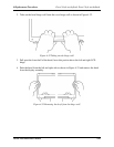
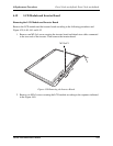
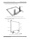
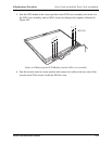
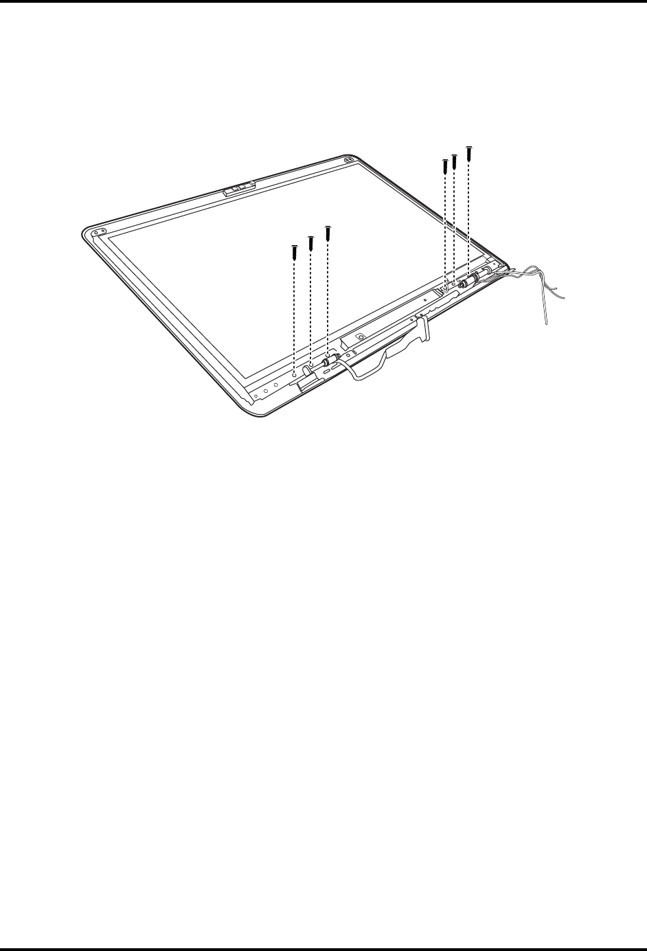
5. Seat the LCD module in the correct position in the LCD cover assembly and secure it to
the LCD cover assembly with six M2x3 screws according to the sequence indicated in
Figure 4.44.
M2x3*6
2
1
3
Figure 4.44 Removing the LCD Module from the LCD cover assembly
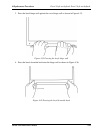
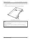
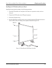
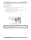
6. Seat the inverter board in correct position and connect two cables to the two ends of the
inverter board. Then secure it with one M2.5x4 screw.
1
2
3
Satellite L500 Maintenance Manual 4-54