


Initial Inspection
TM-XR9B-01XN 2–5
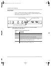
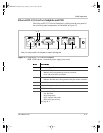
Ethernet/RS-232 Interface Subplate and PCB
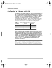
The Ethernet/RS-232 Interface Subplate is visible from the rear panel of
the unit. Rear panel components are identified in Figure 2-2.
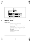
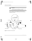
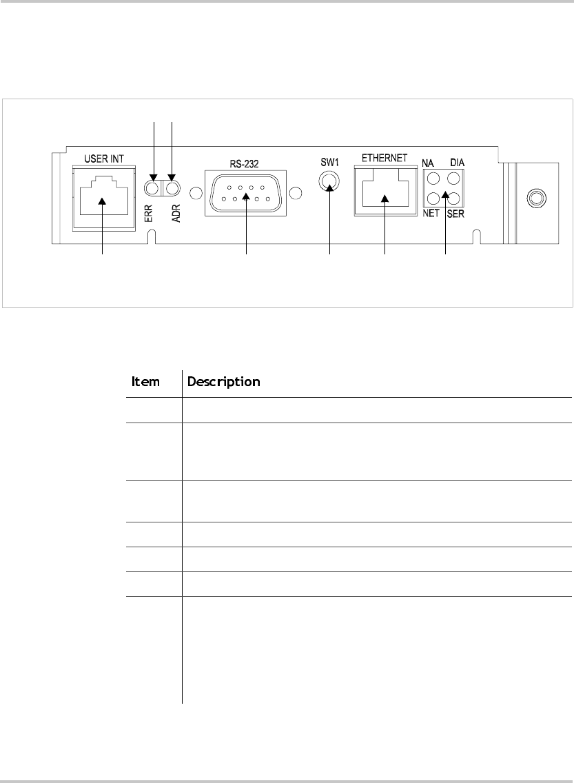
Figure 2-2
Ethernet/RS-232 Interface Subplate
(XFR 1.2kW shown - located on power supply rear cover)
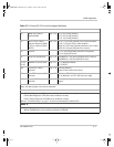
1 User Lines Signal Connector
2 Error LED (ERR)
Indicates that a programming error has occurred.
Clear with error query command.
3 Address LED (ADR)
Indicates that the unit is being addressed by the master controller.
4 RS-232 Connector
5 Ethernet Bridge Reset Switch
6 RJ45 Ethernet Connector
7 Ethernet Bridge LEDs
NA: Reserved
DIA: Diagnostics
NET: Network link status
SER: Serial port activity
See page B–5.
7
2
1
6
Note: On some models, the subplate is rotated 180 degrees.
3
4
5
TM-XR9B-01XN.book Page 5 Monday, April 19, 2004 9:00 AM