


Installation and Configuration
2–6 TM-XR9B-01XN
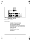
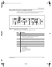
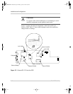
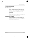
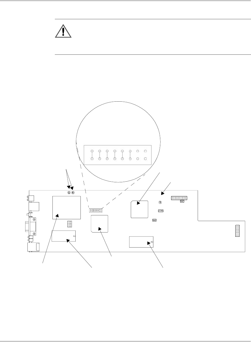
Figure 2-3 shows the internal components on the Ethernet/RS-232
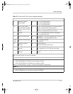
Interface PCB. Table 2-5 shows which jumpers need to be modified to
change modes or settings.
CAUTION
Use proper static control techniques to avoid damage to static-
sensitive components on the printed circuit board
Figure 2-3
Ethernet/RS-232 Interface PCB
Ethernet Bridge
COP LEDs
Slave Controller
Slave EPROM
Master Controller
Master EPROM
J1
J64
J65
1
1
J93
CR89
3
J2
CR166
CR167
J3
1
J103
2
J4
J5
J6
123
COP LED
Subplate
J2
PONREM
NA
NA
XON
FLW
B1
B2
B3
TM-XR9B-01XN.book Page 6 Monday, April 19, 2004 9:00 AM