Installation and Configuration
2–8 TM-XR9B-01XN
Changing Internal Jumpers
Some of the settings on the Ethernet/RS-232 Interface card are user
selectable by way of jumpers on the printed circuit board. The procedure
for changing the jumpers varies depending on if you have a 1.2kW XFR,
or a 2.8kW XFR.
Procedure for 1.2kW XFR
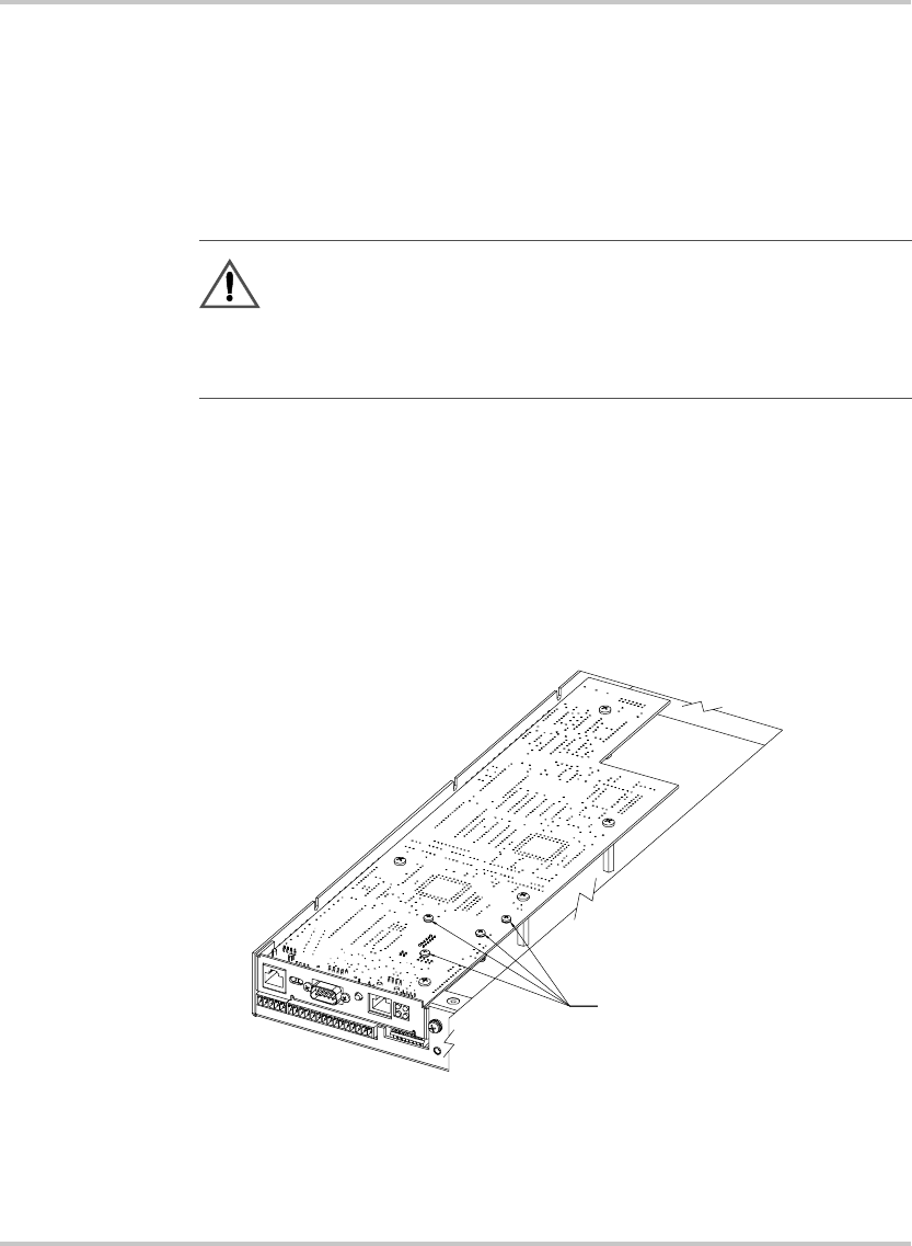
Ensure that the input power connection has been disconnected and the
unit is powered off before you attempt to remove the top cover. Remove
all the screws holding down the top cover and then remove the cover. The
printed circuit board that you need access to is upside down (component
side down), so you must remove all the screws that are holding it in place.
Refer to Figure 2-4 to see which screws should not be removed.
CAUTION
If you remove the unit's cover, use proper static control
techniques to avoid damage to static-sensitive components on
the printed circuit board.
Figure 2-4
Removing the PCB
DURING SERVICE, PLEASE DO NOT
REMOVE THESE SCREWS
During service, do not
remove these screws
TM-XR9B-01XN.book Page 8 Monday, April 19, 2004 9:00 AM


