


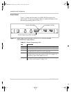
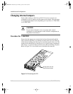
Initial Inspection
TM-XR9B-01XN 2–7
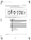
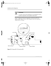
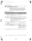
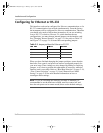
Table 2-2
Ethernet/RS-232 Interface Jumper Selections
J2 Baud rate selection
(default 9600)
page 2–18 B1 (5-6) [closed] [default]
B2 (3-4) [closed] [default]
B3 (1-2) [closed] [default]
J2 RS-232 flow control
selection hardware (RTS/
CTS) or software (XON/
XOFF)
page 2–19 FLW (7-8) [closed] [default] Flow control disabled.
FLW (7-8) [open] Flow control enabled.
XON (9-10) [closed] [default] Hardware flow control.
XON (9-10) [open] Software flow control.
J2 Unused (11-12) [closed] [default] Provides extra jumper.
(13-14) [open] Not used.
J2 Power-On remote/local page 2–20 PONREM (15-16) [open] [default] PON in remote.
PONREM (15-16) [closed] PON in local.
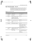
J3, J4,
J5, J6
Ethernet or RS232 mode page 2–12 (2-3) [default] Ethernet.
(1-2) RS232.
J65 Local OVP control
selection
page 2–24 [closed] [default]
[open] Front Panel OVP Control.
J93 User TTL shutdown (S/D)
selection
page 2–25 (1-2) User TTL S/D line active low.
(2-3) [default] User TTL S/D line active high.
J103 Remote OVP control
selection
page 2–24 [closed] [default]
[open]
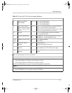
Note: All other jumpers are not user-selectable.
CR89 Red Diagnostic LED Bus error or Soft restart on Master circuitry
CR166 Red Diagnostic LED Soft restart on Master circuitry
CR167 Green Diagnostic LED Bus error on Master circuitry
Refer to “Troubleshooting” on page 3–20 for more information on these LEDs.
Slave EPROM See revision number stamped on EPROM
Master EPROM See revision number stamped on EPROM
TM-XR9B-01XN.book Page 7 Monday, April 19, 2004 9:00 AM