


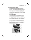

For pinout information, as well as information on how to interconnect to
either a DTE or DCE device, refer to the Appendix.
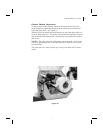
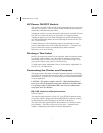
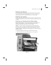
Parallel Interface Requirements
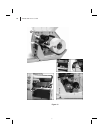
Refer to Figure 6.
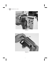
An IEEE 1284 compatible bi-directional parallel data cable is required
when this communication method is selected. The required cable must have
a standard 36-pin parallel connector on one end, which is plugged into the
mating connector located inside the access opening on the left side of the
printer. The parallel interface cable is connected using bail clips instead of
screws.
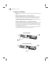
The other end of the parallel interface cable connects to the printer
connector at the host computer.
For pinout information, refer to the Appendix.
Serial and Parallel Cabling Requirements
Data cables must be fully shielded and fitted with metal or metallized
connector shells. Shielded cables and connectors are required to prevent
radiation and reception of electrical noise.
To minimize electrical noise pickup in the cable:
1. Keep data cables as short as possible.
2. Do not bundle the data cables tightly with power cords.
3. Do not tie the data cables to power wire conduits.
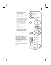
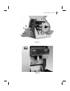
Communicating with the Printer
Via the Parallel Port
Set the parallel connection on the host computer. For instructions, refer
to your computer’s user’s guide.
Via the Serial Port
Set the host computer to the factory defaults of the printer: 9600 baud, 8
bit word length, no parity, 1 stop bit, and XON/XOFF. For instructions,
refer to your computer’s user’s guide.
NOTE: If you can’t reset the host computer communications settings, then
you must establish a temporary parallel connection to send down the Set
Communications (^SC) command that changes the printer’s settings to
match the host settings.
DEFAULTING THE PRINTER: To reset only the communications
parameters on the printer to the factory defaults (9600 baud, 8 bit word
S400 & S600 User’s Guide 19
27