


DUA1840-0AAA01
4-10
C
H
A
P
T
E
R
4:
A
D
V
A
N
C
E
D
M
A
N
A
G
E
M
E
N
T
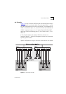
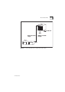
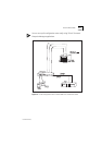
Example 3
The example shown in
Figure 4-4
illustrates two VLANs spanning three
Switch 1005s (each with a 100FX Transceiver Module as port 1) and a
basement SuperStack II Switch 3000 FX with a 100FX Downlink Module.
Each Switch 1005 connects into the basement Switch 3000 FX using a
VLT. The attached router allows the two VLANs to communicate with
each other.
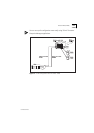
To set up this configuration:
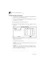
1
Use the VT100 screens to:
a
Place ports 5-8 of all the Switch 1005s in VLAN 1.
b
Place ports 9-12 of all the Switch 1005s in VLAN 2.
2
Connect port 1 on each Switch 1005 to a port in the Switch 3000 FX.
3
Use the VT100 screens to:
a
Specify that port 1 on each Switch 1005 is a backbone port.
b
Specify that port 1 on each Switch 1005 is part of a VLT.
c
Specify that each Switch 3000 FX port connected to a Switch 1005 is
part of a VLT.
4
Connect port 1 of the Switch 3000 FX to Server 1.
5
Connect port 2 of the Switch 3000 FX to Server 2.
6
Use the VT100 screens to:
a
Place port 1 of the Switch 3000 FX in VLAN 1.
b
Place port 2 of the Switch 3000 FX in VLAN 2.
7
Connect two spare ports on the Switch 3000 FX to the router.
8
Use the VT100 screens to specify that one Switch 3000 FX port
connected to the router is placed in VLAN 1, and the other is placed in
VLAN 2.