


DUA1840-0AAA01
6-2
C
H
A
P
T
E
R
6:
P
R
O
B
L
E
M
S
O
L
V
I
N
G
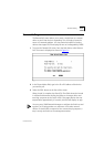
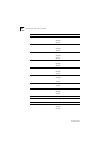
Identifying Fault Conditions with the LEDs
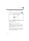
The following table shows how you can identify possible fault
conditions that may occur during normal operation. It also describes
actions that may resolve the problem:
If you cannot solve the problem, contact your local supplier, or proceed
as described in
Appendix C
.
LED
Color
Indicates
Try the following actions
PWR
(Power)
Off
Power is not reaching the module ■
Check that the Power LED on the
MSH chassis is not lit red. If it is,
refer to your chassis user
documentation.
■
Ensure the MSH chassis is
powered-up correctly with all
power leads securely connected.
■
Ensure the module is fully
engaged into the chassis.
■
Contact your supplier for advice.
Faulty LED ■
Test LEDs to confirm.
Amber
Fault occurred on this module
during POST or normal operation
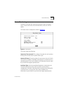
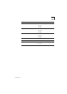
BACKPLANE
E, FE
Off
Fault
Faulty LED
■
Ensure module is fully engaged
into chassis and the backplane
connectors are fully mated.
■
Test LEDs to confirm.
1 - 12
(External port
status)
Off
Fault ■
Check all connections are secure.
■
Check all cables and connectors
for signs of damage.