


DUA1840-0AAA01
Pre-installation Configuration
2-3
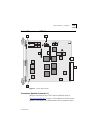
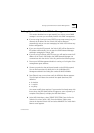
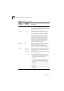
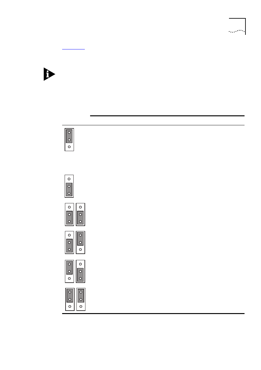
Table 2-1
shows possible configurations for LK1 - LK5. You may have
any combination of backplane connections enabled at any one time.
In a managed MSH chassis, these links will be overridden by any
changes made through management software. This is the case, even if
the chassis is reset or powered off/on, or if the Switch 1005 module is
replaced with another one.
Table 2-1
Setting LK1 - LK5 for internal port connections
Position and Link Number
Connection Provided
LK1 ENABLED
LK2 ENABLED
LK3 ENABLED
Switch port 25 connected to
10Mbps Ethernet backplane E1.
Switch port 26 connected to
10Mbps Ethernet backplane E2.
Switch port 27 connected to
10Mbps Ethernet backplane E3.
LK1, LK2, LK3 DISABLED
None
LK4 DISABLED, LK5 DISABLED
Switch port 28 disabled
LK4 DISABLED, LK5 ENABLED
Switch port 28 connected to
100Mbps Fast Ethernet backplane.
This allows you to interconnect
multiple Switch 1005 modules.
LK4 ENABLED, LK5 DISABLED
Reserved for future use.
LK4 ENABLED, LK5 ENABLED
Reserved for future use.