


Physical Features 15
Table 6 SFP Mode SFP/Duplex Status LEDs
The SFP module will only disable the 1000BASE-T
interface once there is a valid link on the module.
(7) Power LED
The Power LED shows the power status of the Switch.
Table 7 Power Status LED
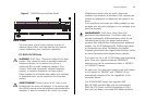
(8) Self-adhesive Pads
The unit is supplied with four self-adhesive rubber pads.
Do not apply the pads if you intend to rack mount the
unit.
If the unit is to be part of a free-standing stack, apply
the pads to each marked corner area on the underside
of the unit. Place the unit on top of the lower unit,
ensuring that the pads locate within the recesses of the
lower unit.
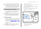
Rear Panel
The rear panel of the Switch contains the power supply
socket.
(9) Power Socket
The Switch automatically adjusts to the supply voltage.
Only use the power cord that is supplied with the unit.
SFP/Duplex Meaning
Green The SFP module is inserted, regardless of
the link status.
Off The SFP module is not inserted.
Status Meaning
Green The unit is powered on and ready for use.
Yellow Internal power, POST, or loopback test has
failed. Switch is in fail-safe mode.
Flashing The Switch is undergoing the power up
sequence, or a software upgrade is underway.
Off The unit is not receiving power.
■ Check that the power cord is connected
correctly.
■ If the unit still does not operate, contact your
supplier.