


Interpreting Hub Indicators 2-5
7 Apply power to the hub in either of these ways:
■ Plug one end of the power cord into the AC input socket and the
other end into a power source.
■ Connect the hub to a power supply, as described in “Using Optional
Power Systems” later in this chapter.
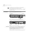
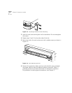
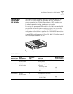
Placing on a Desktop If you place the hub on a desk or table, attach the supplied rubber feet to
each bottom corner of the hub. Remove the protective cap from each
downlink port and attach the proper cable to make the desired network
connection. (For connector and cable information, see Table 2-1. For
guidelines on making typical connections, see Chapter 3.) Apply power
to the hub in either of these ways:
■ Plug one end of the power cord into the AC input socket and the
other end into a power source.
■ Connect the hub to a power supply, as described in “Using Optional
Power Systems” later in this chapter.
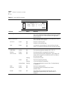
Interpreting Hub
Indicators
When power is applied, all the indicators on the front panel light
momentarily. The UNIT STATUS LED is amber while POST is running.
After approximately 30 seconds, the UNIT STATUS LED turns green.
Verify that the PWR (power) LED remains lit, indicating that the hub
is receiving power.
For explanations of the hub indicators, see Table 2-2.
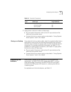
Table 2-1 Downlink Connections
Connector
Type
Cable Type
Maximum Cable
Length (Meters)
SC Short-wavelength (850 nm) fiber-optic:
62.5/125 µ MMF
50/125 µ MMF
260
550