


1-2
C
HAPTER
1: I
NTRODUCTION
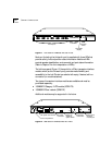
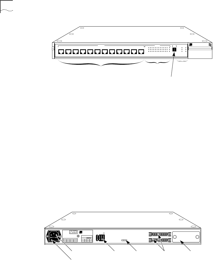
Figure 1-1
Front Panel of LinkBuilder FMS 100-TX Hub
Each port (including the thirteenth port) is supplied with three LEDs that
provide activity, link, and partition status information. Additional LEDs
provide repeater classification, environmental, and port status information.
(Refer to Chapter 3 for the interpretation of LEDs.)
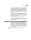
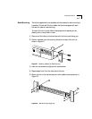
The hub’s rear panel (Figure 1-2) has a slot for a 3Com transceiver interface
module, which (as the thirteenth port) provides media flexibility and
accessibility to the hub. This slot can also be left empty, if desired, with no
connection (no module attached).
Two types of transceiver interface modules are available and must be
purchased separately:
■
100BASE-TX Category 5 UTP module (3C252-TX)
■
100BASE-FX Fiber module (3C262-FX)
Additional modules may be supported in the future.
Figure 1-2
Rear Panel of LinkBuilder FMS 100-TX Hub
®
1x 2x 3x 4x 5x 6x 7x
100BASE-TX STATUS
8x 9x 10x 11x 12x
12345678910111213
ACTIVITY
UNIT
LINK
PARTITION
CLSII
3C250-TX/Ι
CLSI
PWR
FAN FAIL
OVERTEMP
COLLISION
100BASE-TX Hub
LinkBuilder FMS 100
RJ-45 ports
Port LEDs
Unit digital
display
Hub
operation
LEDs
!
®
3Com Corporation
Santa Clara, CA
Made in USA
REFER TO
INSTRUCTION MANUAL
FOR CORRECT
SELECTION OF
POWER CORD
CAUTION: For continued
protection against risk of fire
use only with same type
and rating of anti-serge fuse.
INPUT
V
A max
5
5.0
+12
2.5
–12
0.2
UP
DOWN
EXPANSION
DC INPUT
ED
AC power cord socket
Fuse compartment
DC input
connector
Power-up
disabled
option switch
Expansion
connectors
Transceiver
interface
module port