


3
MAKING FMS 100-TX HUB
C
ONNECTIONS
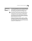
This chapter discusses how to use the LinkBuilder FMS 100-TX Hub in
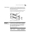
various network environments. The chapter also discusses how to interpret
the hub’s LEDs and how to use the power-up disabled option.
Making Network
Connections
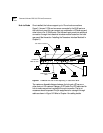
Table 3-1 summarizes the possible schemes for connecting the LinkBuilder
FMS 100-TX Hub in a 100BASE-T network. These connections are the only
ones permitted for a Class I device such as the LinkBuilder FMS 100-TX Hub.
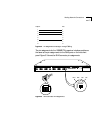
Connections that use the 100BASE-TX module are identical to those that use
an RJ-45 port on the hub’s front panel.
Table 3-1 LinkBuilder FMS 100-TX Hub Network Connections
Hub Connection Connectors Cabling Required Purpose
To node RJ-45 port
Transceiver interface module:
100BASE-TX
100BASE-FX
Straight-through UTP
Straight-through UTP
Fiber
Connects PCs, servers, and other
network devices directly to the hub
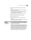
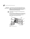
To another hub in the
stack
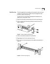
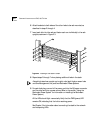
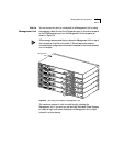
Expansion connector Expansion cable Connects as many as eight hubs
to each other to form a single
logical stack
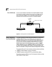
To Management Unit Expansion connector Expansion cable Connects hub or hub stack to a
Management Unit
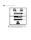
To network backbone Transceiver interface module:
100BASE-TX
100BASE-FX
RJ-45 port
Straight-through or
cross-over UTP depending
on device
Fiber
Straight-through or
cross-over UTP depending
on device
Connects hub or hub stack to
network backbone through a
bridge, router, or switch