


2-8 CHAPTER 2: INSTALLING THE FMS 100-TX HUB
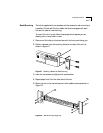
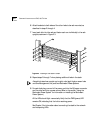
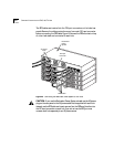
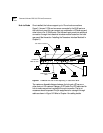
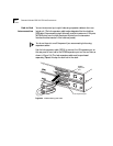
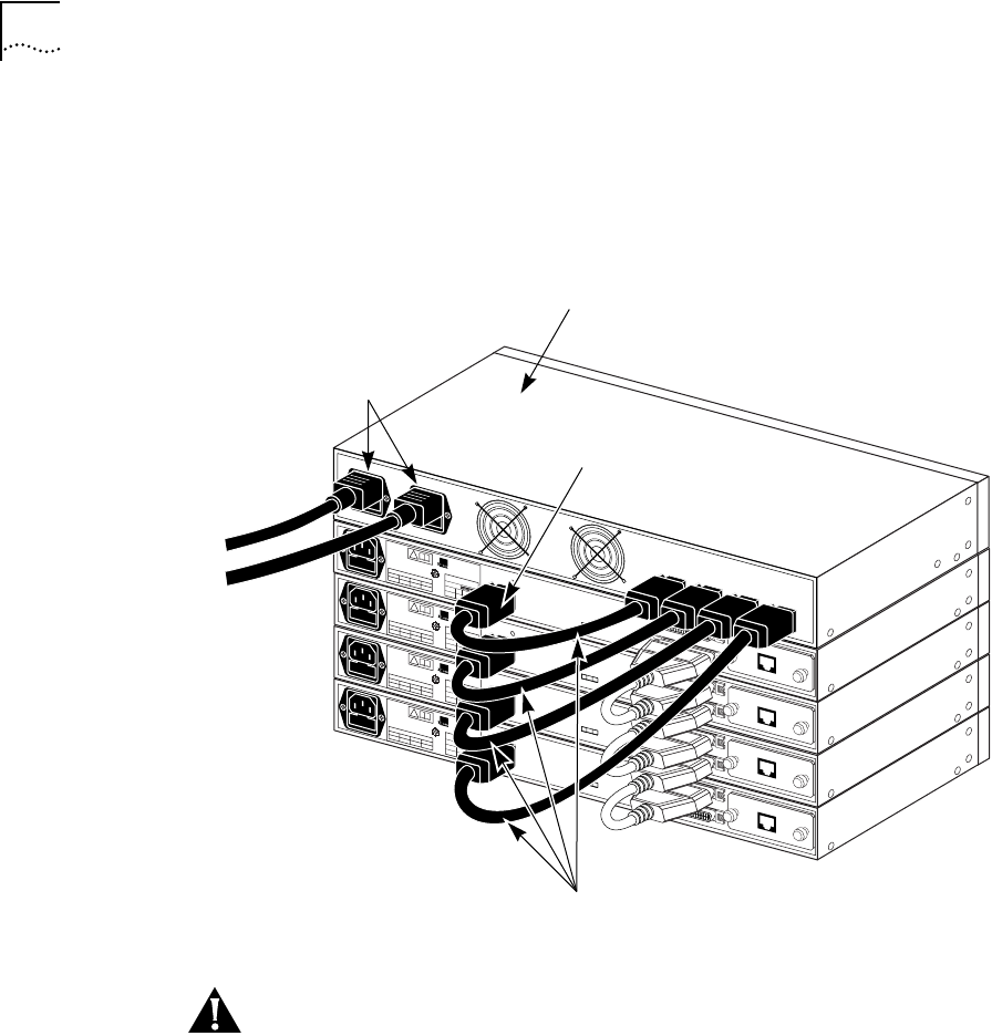
The RPS cables are inserted into the DC input connectors on the hubs’ rear
panels. Remove the rubber protective cover from each DC input connector
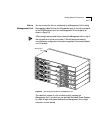
before connecting the RPS cable. Figure 2-6 shows the RPS mounted on top
of a four-hub stack and connected to each hub.
Figure 2-6 Connecting the Redundant Power System to Four Hubs
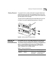
CAUTION: If you use the Redundant Power System, do not use the AC power
plug on the rear panel or the AC power cable that is supplied with each hub.
Instead, use the RPS cable and insert one end into the RPS and the other into
the DC input connector on each hub. If you do not use the RPS, you must
connect each hub separately to an AC power source.
!
®
3Com Corporation
Santa Clara, CA
Made in USA
REFER TO
INSTRUCTION MANUAL
FOR CORRECT
SELECTION OF
POWER CORD
CAUTION: For continued
protection against risk of fire
use only with same type
and rating of anti-serge fuse.
INPUT
V
A max
5
5.0
+12
2.5
–12
0.2
EXPANSION
OUT
IN
DC INPUT
E
D
!
®
3Com Corporation
Santa Clara, CA
Made in USA
REFER TO
INSTRUCTION MANUAL
FOR CORRECT
SELECTION OF
POWER CORD
CAUTION: For continued
protection against risk of fire
use only with same type
and rating of anti-serge fuse.
INPUT
V
A max
5
5.0
+12
2.5
–12
0.2
OUT
IN
EXPANSION
DC INPUT
E
D
!
®
3Com Corporation
Santa Clara, CA
Made in USA
REFER TO
INSTRUCTION MANUAL
FOR CORRECT
SELECTION OF
POWER CORD
CAUTION: For continued
protection against risk of fire
use only with same type
and rating of anti-serge fuse.
INPUT
V
A max
5
5.0
+12
2.5
–12
0.2
EXPANSION
OUT
IN
DC INPUT
E
D
!
®
3Com Corporation
Santa Clara, CA
Made in USA
REFER TO
INSTRUCTION MANUAL
FOR CORRECT
SELECTION OF
POWER CORD
CAUTION: For continued
protection against risk of fire
use only with same type
and rating of anti-serge fuse.
INPUT
V
A max
5
5.0
+12
2.5
–12
0.2
OUT
IN
EXPANSION
DC INPUT
E
D
AC power
cords
RPS cables
DC input
connector
Redundant
Power
System