


3-12 CHAPTER 3: MAKING FMS 100-TX HUB CONNECTIONS
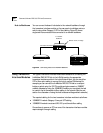
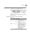
Operation LEDs Table 3-3 interprets the meaning of the hub operation LEDs.
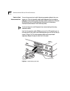
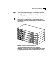
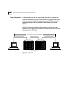
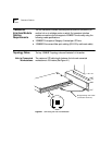
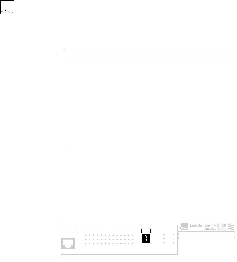
Unit Digital Display The front panel unit digital display (see Figure 3-11) provides a numeric
designation for each component in a hub stack, including a Management Unit
if one is present. Unit numbers are assigned dynamically as the units are
plugged into the stack. The Management Unit ID is assigned after the
Power-On Self-Test (POST) has run. The number 1 indicates the device that has
no other unit above it; in other words, the hub (or Management Unit) that is on
the top of the stack and connected by a hub expansion cable to the
component immediately below it.
Figure 3-11 Unit Digital Display
Table 3-3 Hub Operation LEDs
LED Color Status Meaning
FAN FAIL Amber ON One or both of the two internal fans
have failed.
OVERTEMP Amber ON The internal temperature exceeds 158° F
(70° C).
COLLISION Green ON The segment is experiencing collisions.
CLS II (Class II) OFF The FMS 100-TX Hub does not support
Class II configuration. This LED is
nonfunctional.
CLS I (Class I) Green ON The FMS 100-TX Hub supports Class I
configuration, which means that only
one repeater or hub stack can be used
between two end stations.
PWR (Power) Green ON The hub is receiving power.
12x
UNIT
STATUS
12345678910111213
ACTIVITY
LINK
PARTITION
CLSII
3C250-TX/Ι
CLSI
PWR
FAN FAIL
OVERTEMP
COLLISION
®