4-2 CHAPTER 4: CABLING
Transceiver
Interface Module
Cabling
Requirements
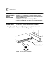
The two transceiver interface modules provide downlink connectivity to
another hub or to a bridge, router, or switch. For transceiver interface
module connections, the hub supports 100BASE-T functionality using the
following media specifications:
■ 100BASE-TX: two pairs of Category 5 twisted-pair UTP wire
■ 100BASE-FX: two-strand fiber-optic cabling (62.5/125 µ multimode cable)
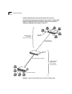
Topology Rules The key 100BASE-T topology rules are illustrated in this section.
Hub to Connected
Workstations
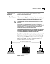
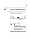
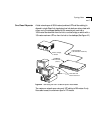
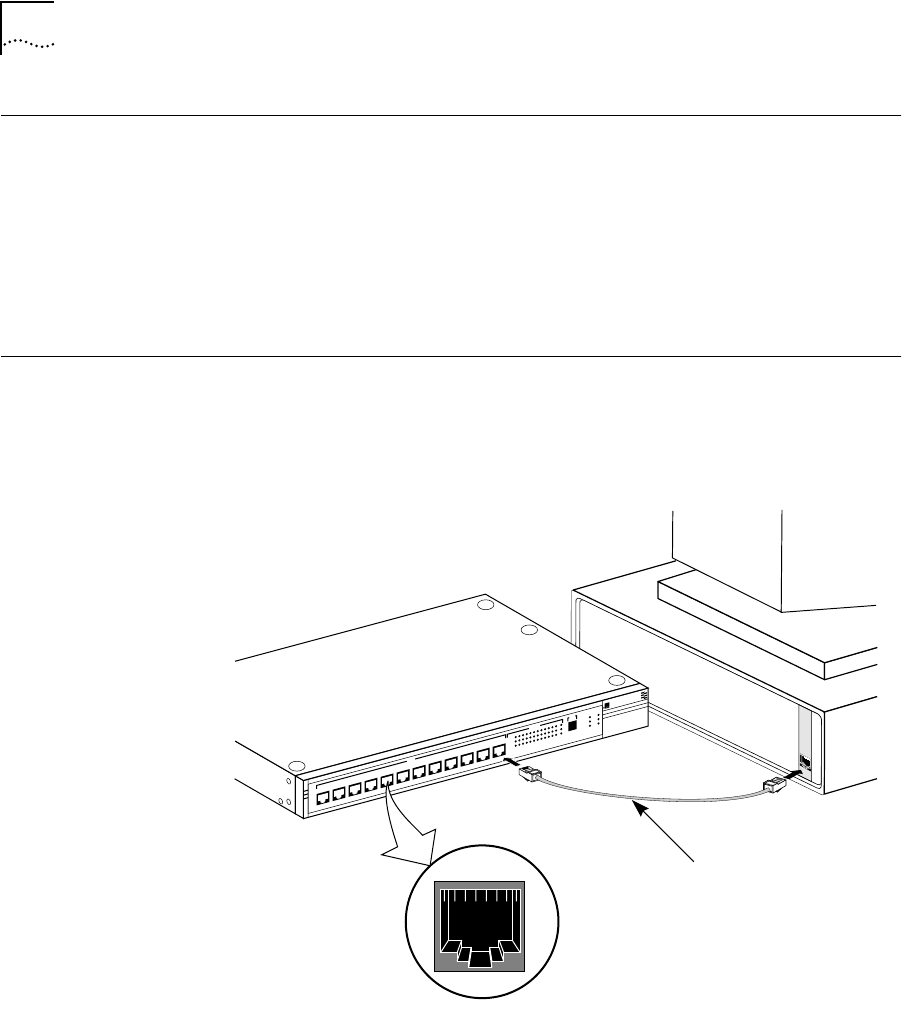
The maximum UTP cable length between the hub and connected
workstations is 100 meters. (See Figure 4-1.)
Figure 4-1 Connecting the Hub to a Workstation
Straight-through UTP cable
(100 meters maximum)
1 . . . . . . .8
®
LinkBuilder FMS 100
100BASE-TX Hub
1x
2x
3x
4x
5x
6x
7x
100BT STATUS
8x
9x
10x
11x
12x
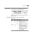
12345678910111213
ACTIVITY
UNIT
LINK
PARTITION
CLSII
3C250-TX/Ι
CLSI
PWR
FAN FAIL
OVERTEMP
COLLISION


