


2-4 CHAPTER 2: INSTALLING THE FMS 100-TX HUB
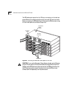
6 Attach brackets to both sides of the other hubs to be rack-mounted, as
described in steps 2 through 4.
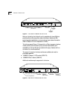
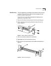
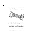
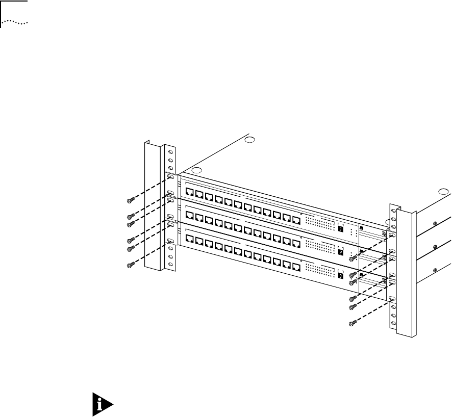
7 Insert each hub into the rack and fasten each one individually to the rack
uprights, as shown in Figure 2-3.
Figure 2-3 Installing a Hub Stack in a Rack
8 Repeat steps 2 through 7 when placing additional hubs in the stack.
A single hub stack can contain up to eight units (eight hubs, or seven hubs
and one Management Unit) and two Redundant Power Systems.
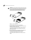
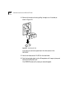
9 For each hub, plug one end of the power cord into the AC power connector
and the other end into a power source. (Refer to the section “Using the
Redundant Power System” for information on installing the Redundant
Power System.)
All the LEDs should light momentarily. Verify that the PWR (power) LED
remains ON, indicating that the hub is receiving power.
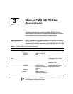
See Chapter 3 for information about connecting the stack to the network
and interpreting LEDs.
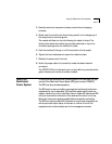
®
1x
2x
3x
4x
5x
6x
7x
100BT
STATUS
8x
9x
10x
11x
12x
12345678910111213
ACTIVITY
UNIT
LINK
PARTITION
CLSII
3C250-TX/
Ι
CLSI
PWR
FAN FAIL
OVERTEMP
COLLISION
®
1x
2x
3x
4x
5x
6x
7x
100BT
STATUS
8x
9x
10x
11x
12x
12345678910111213
ACTIVITY
UNIT
LINK
PARTITION
CLSII
3C250-TX/
Ι
CLSI
PWR
FAN FAIL
OVERTEMP
COLLISION
®
1x
2x
3x
4x
5x
6x
7x
100BT
STATUS
8x
9x
10x
11x
12x
12345678910111213
ACTIVITY
UNIT
LINK
PARTITION
CLSII
3C250-TX/
Ι
CLSI
PWR
FAN FAIL
OVERTEMP
COLLISION
LinkBuilder FMS 100
LinkBuilder FMS 100
LinkBuilder FMS 100
100BASE-TX Hub
100BASE-TX Hub
100BASE-TX Hub