


Installing the Transceiver Interface Modules 2-5
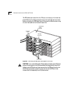
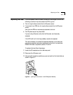
Desktop Placement If you place the hub on a desk or table, attach the supplied rubber feet to
each bottom corner of the hub. If you stack additional hubs on top of the
bottom one, place rubber feet on the bottom of each corner of each hub in
the outline shown on the unit’s base.
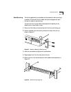
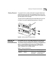
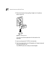
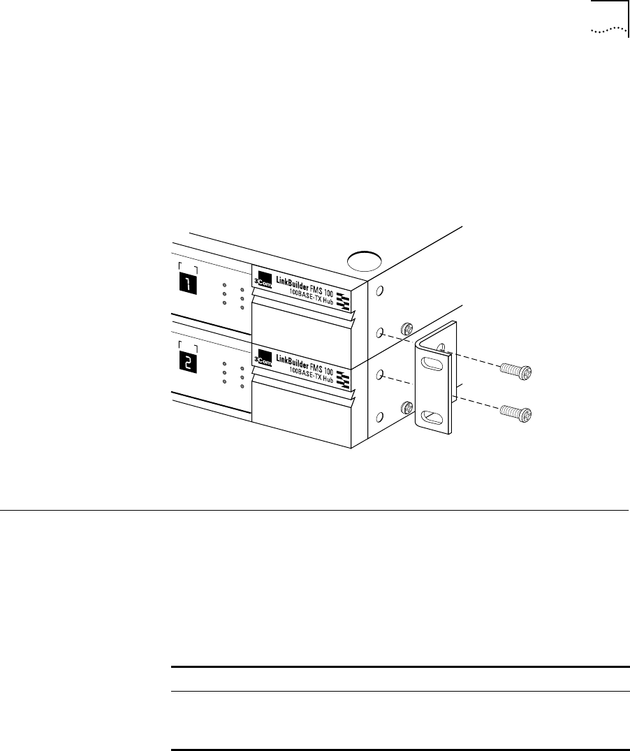
To prevent hubs from possibly sliding off the stack, fasten each hub to the
hub below it by using the supplied brackets, as shown in Figure 2-4.
Figure 2-4 Attaching a Bracket for Desktop Placement
Installing the
Transceiver
Interface Modules
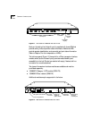
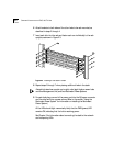
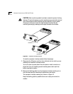
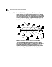
The LinkBuilder FMS 100-TX Hub chassis is equipped with a rear panel port
into which you can insert an optional 3Com transceiver interface module.
The transceiver interface module permits connections to a 100 Mbps Ethernet
station or a network backbone that is also running 100 Mbps Ethernet.
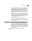
The two types of transceiver interface modules are shown in Figure 2-5.
Table 2-1 describes the two 100 Mbps modules.
UNIT
CLSII
3C250-TX/Ι
CLSI
PWR
FAN FAIL
OVERTEMP
COLLISION
UNIT
CLSII
3C250-TX/Ι
CLSI
PWR
FAN FAIL
OVERTEMP
COLLISION
®
®
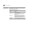
Table 2-1 Transceiver Interface Modules
Module Type 3Com Part Number Connector Cabling
100BASE-TX 3C252-TX RJ-45 Category 5 UTP cabling
100BASE-FX 3C262-FX Multimode fiber
SC connector
Two-strand (62.5/125µ)
fiber-optic cabling