


Power-Up Disabled Option Switch 3-13
Power-Up
Disabled Option
Switch
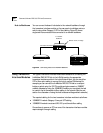
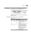
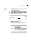
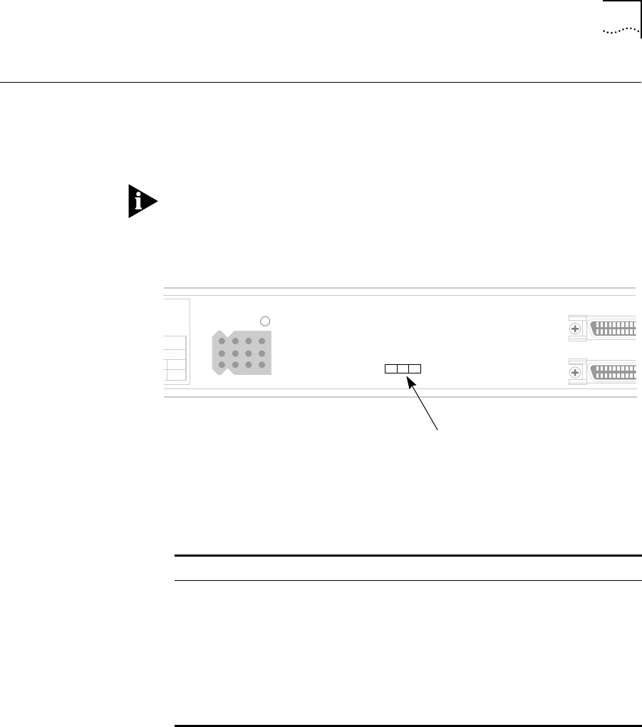
If network management is present, an external switch on the hub’s rear panel
allows you to power-up the hub with the ports disabled. The power-up
disabled option switch is located between the expansion connectors and the
DC input connector, as shown in Figure 3-12.
This feature cannot be fully implemented unless a network management
device (such as the LinkBuilder FMS 100 Management Unit) is connected to
the hub stack. If no network management is present, leave the power-up
disabled option switch in the enabled position (set to E).
Figure 3-12 Power-Up Disabled Option Switch
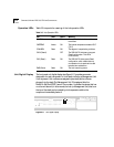
Table 3-4 describes the functioning of the power-up disabled option switch.
You can use this option for security purposes. For example, you can disable a
port where a faulty device or other problem exists. This prevents the disabled
port from receiving any data when the hub is powered-up. Conversely, you
can enable ports if you want them to receive data.
tion
A
–12
0.2
UP
DOWN
EXPA
DC INPUT
ED
Power-up disabled
option switch
Table 3-4 Settings on Power-Up Disabled Option Switch
Setting Result
D (disabled) If network management is present, you can enable specific ports
after the hub has been powered-up.
If network management is not present, all ports remain disabled
after the hub has been powered-up.
E (enabled) This is the default setting. All ports are enabled after the hub has
been powered-up, whether or not network management is present.
If network management is present, individual ports can then be
disabled after the hub has been powered-up.