


vii
F
IGURES
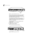
1-1
Front Panel of LinkBuilder FMS 100-TX Hub 1-2
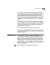
1-2
Rear Panel of LinkBuilder FMS 100-TX Hub 1-2
2-1
Attaching a Bracket for Rack Mounting 2-3
2-2
Rack Mounting a Single Hub 2-3
2-3
Installing a Hub Stack in a Rack 2-4
2-4
Attaching a Bracket for Desktop Placement 2-5
2-5
Transceiver Interface Modules 2-6
2-6
Connecting the Redundant Power System to Four Hubs 2-8
2-7
Opening the Fuse-holder in the AC Receptacle Assembly 2-9
2-8
Removing the Fuse 2-10
3-1
LinkBuilder FMS 100-TX Hub Supporting 11 Users and a Server 3-2
3-2
Pin Assignments for Straight-Through Cabling 3-3
3-3
RJ-45 Connector Pin Assignments 3-3
3-4
Interconnecting Two Hubs 3-4
3-5
Connecting a Hub Stack to a Management Unit 3-5
3-6
Connecting Hubs to the Network Backbone 3-6
3-7
10 and 100 Mbps Collision Domains Connected by a Switching Hub 3-8
3-8
Class I Hub 3-9
3-9
Class II Hubs 3-10
3-10
LED Indicators 3-11
3-11
Unit Digital Display 3-12
3-12
Power-Up Disabled Option Switch 3-13
4-1
Connecting the Hub to a Workstation 4-2
4-2
Connecting the Hub in a Network Span of 260.8 Meters 4-3
4-3
Using an Internetworking Device to Extend the Network Span 4-4