


661 Brea Canyon Rd., Suite 3
Walnut, CA 91789
tel: 909.598.7388, fax: 909.598.0218
© Copyright 2009 Acnodes, Inc.
All rights reserved. Product description and product specifications
are subject to change without notice. For latest product information,
please visit Acnodes’ web site at www.acnodes.com.
RMC 7132
1U Rackmount System
CHAPTER 3 SYSTEM INTERFACE
3-1 Overview
There are several LEDs on the control panel to keep you constantly informed of the overall status of the
system as well as the activity and health of specific components. There are also two buttons on the control
panel. This chapter explains the meanings of all LED indicators and the appropriate response you may
need to take.
3-2 Control Panel Buttons
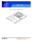
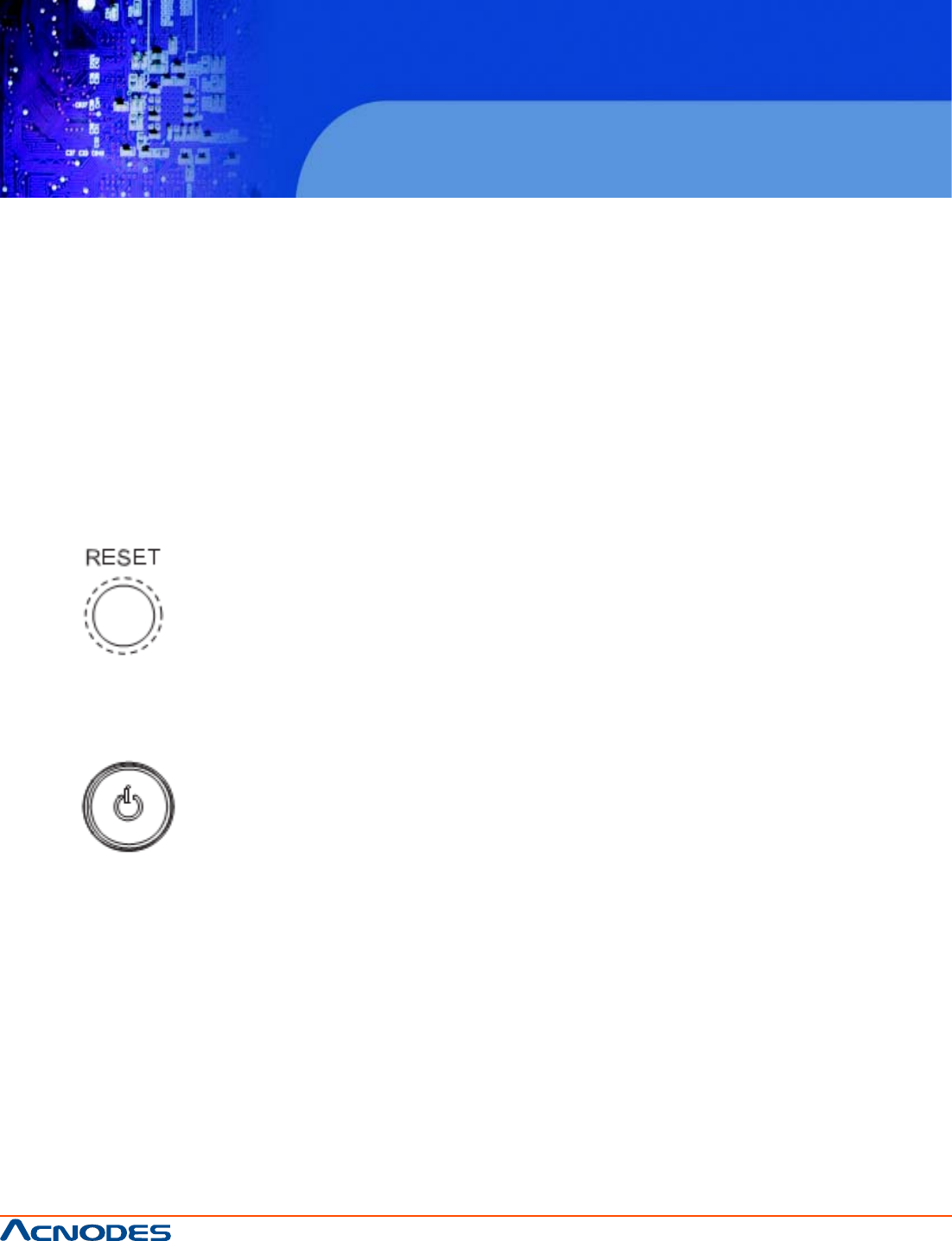
There are two push buttons located on the front of the chassis: a reset button and a power on/off button.
Reset Button
The reset button reboots the system.
Power
This is the main power button, which is used to apply or turn off the main system power. Turning off system
power with this button removes the main power but keeps standby power supplied to the system. If you
need to service the system you should unplug the AC power cord after shutting down the server.
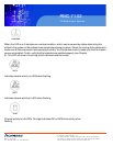
3-3 Control Panel LEDs
The control panel located on the front of the chassis has five LEDs. These LEDs provide you with critical
information related to different parts of the system. This section explains what each LED indicates when
illuminated and any corrective ac- tion you may need to take.