


661 Brea Canyon Rd., Suite 3
Walnut, CA 91789
tel: 909.598.7388, fax: 909.598.0218
© Copyright 2009 Acnodes, Inc.
All rights reserved. Product description and product specifications
are subject to change without notice. For latest product information,
please visit Acnodes’ web site at www.acnodes.com.
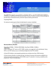
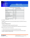
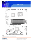
RMC 7132
1U Rackmount System
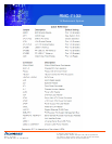
5-9 Connector Definitions
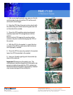
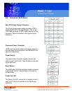
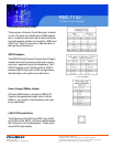
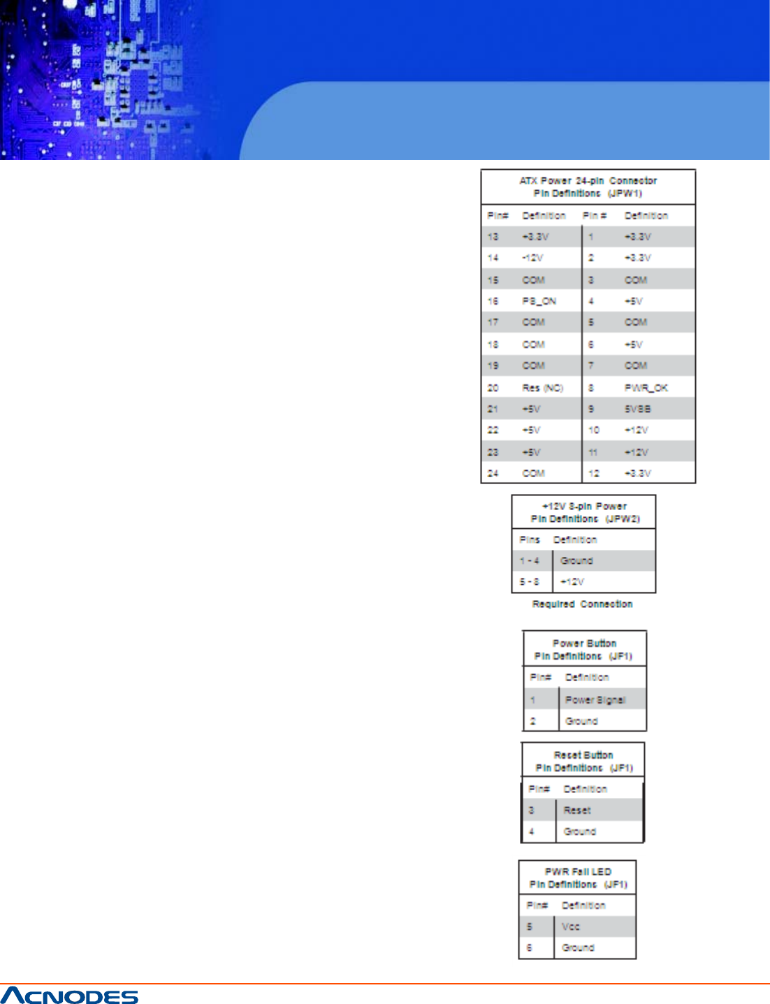
Main ATX Power Supply Connector
The 24-pin primary power supply connector (JPW1)
meets the SSI EPS 12V specification. The 8 - pin
CPU PWR connector (JPW2) is also required for the
processor. Refer to the table on the right for the pin
definitions.
Processor Power Connector
JPW2 must also be connected to the power supply to
provide power for the processor. See the table on the
right for pin definitions.
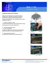
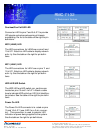
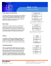
Power Button
The power button (from the computer chassis) con-
nects to pins 1 and 2 of JF1. See the table on the right
for pin definitions.
Reset Button
The reset button (from the computer chassis) connects
to pins 3 and 4 of JF1. See the table on the right for
pin definitions.
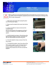
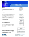
Power Fail LED
The Power Fail LED connection is located on pins 5
and 6 of JF1. Re- fer to the table on the right for pin
definitions.